Section 10 STEERING SYSTEM
Subsection 01 (STEERING SYSTEM)
1
F19J0CA
2
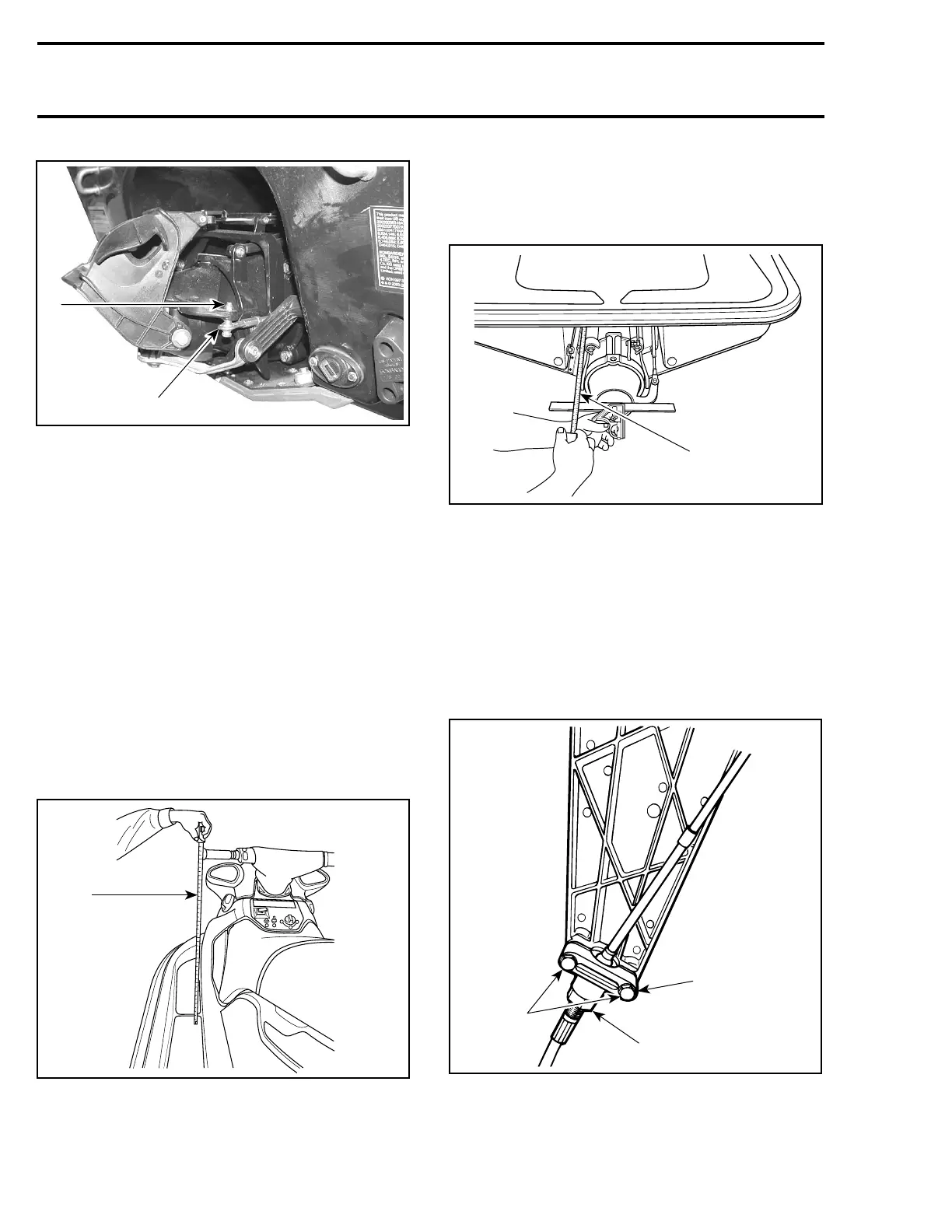
TYPICAL
1. Ball joint below steering arm
2. Torque nut to 7 N•m(62lbf•
in)
Nozzle
Installnozzleonventuriandtorqueboltsto
24 N•m(17lbf•ft).
Install reverse spring and reverse gate.
Connect steering cable and perform steering align-
ment.
After assembling procedure, adjust throttle cable
then perform a steering alignment.
STEERING ALIGNMENT
Position handlebar in straight ahead position by
measuring each side the distance from handlebar
grip end to floorboard.
F01K07A
1
TYPICAL
1. Measuring handlebar grip end/floorboard distance
Check jet pump nozzle position by placing a
straight edge on nozzle outer end. Measure the
distance on each side of the straight edge. It
must be equalled.
F01J5ZA
1
TYPICAL
1. Measure the distance on each side of the straight edge
If necessary, steering alignment adjustment
should be performed at steering cable support.
Open storage compartment cover.
Remove access panel.
Loosen2boltsretainingblockno. 20 at cable sup-
port no. 23.
Turn adjustment nut as required.
1
3
F01K18A
2
1. Retaining block
2. Adjustment nut
3. Loosen bolts
284 smr2005-066