Section 03 ENGINE SYSTEM
Subsection 03 (REMOVAL AND INSTALLATION)
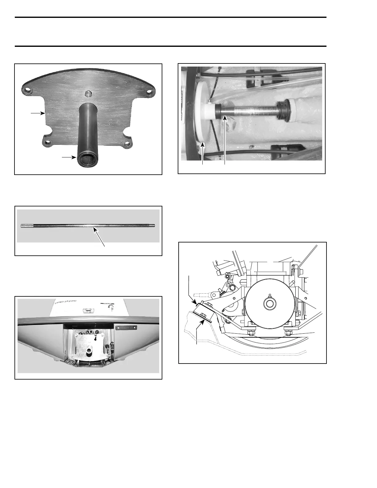
F19J09A
1
2
1. Plate
2. Support
– alignment shaft (P/N 295 000 141)
F00B0GA
1
1. Alignment shaft
To verify alignment proceed as follows:
– Install the appropriate plate with the support to
hull with four nuts.
F00B0HA
– Carefully slide shaft through support.
– Insert shaft end into PTO flywheel.
NOTE: Ensure the protective hose and carbon ring
(or seal carrier) is removed to check engine align-
ment.
NOTE: If the alignment is correct, the shaft will
slide easily without any deflection in PTO fly-
wheel.
F07D05A
2 1
TYPICAL
1. Alignment shaft
2. PTO flywheel
If the alignment is incorrect loosen engine support
screws to enable to align PTO flywheel with shaft
end.
NOTE: Use shim(s) as necessary to correct align-
ment.
A
B
smr2005-049-004_a
717 ENGINES
66
smr2005-049