Section09PROPULSION
Subsection 02 (DRIVE SYSTEM)
F00J04B
1
1. Spacer
NOTE: Drive shaft must be removed to install
spacer.
INSTALLATION
Installation is essentially the reverse of removal
procedure. However, pay particular attention to
the following.
Drive Shaft and Dampers
Install dampers no. 13 on drive shaft no. 9.
NOTE: Make sure dampers were not left in PTO
flywheel or impeller.
Install drive shaft and jet pump at the same time.
Insert drive shaft through carbon ring no. 11 and
floating ring no. 6.
NOTE: Make sure to install floating ring before
inserting the drive shaft in the PTO flywheel.
While holding jet pump, guide and engage drive
shaft splines in PTO flywheel. Rotate shaft to
properly index splines. Make sure boot no. 2 is
well positioned over shaft end.
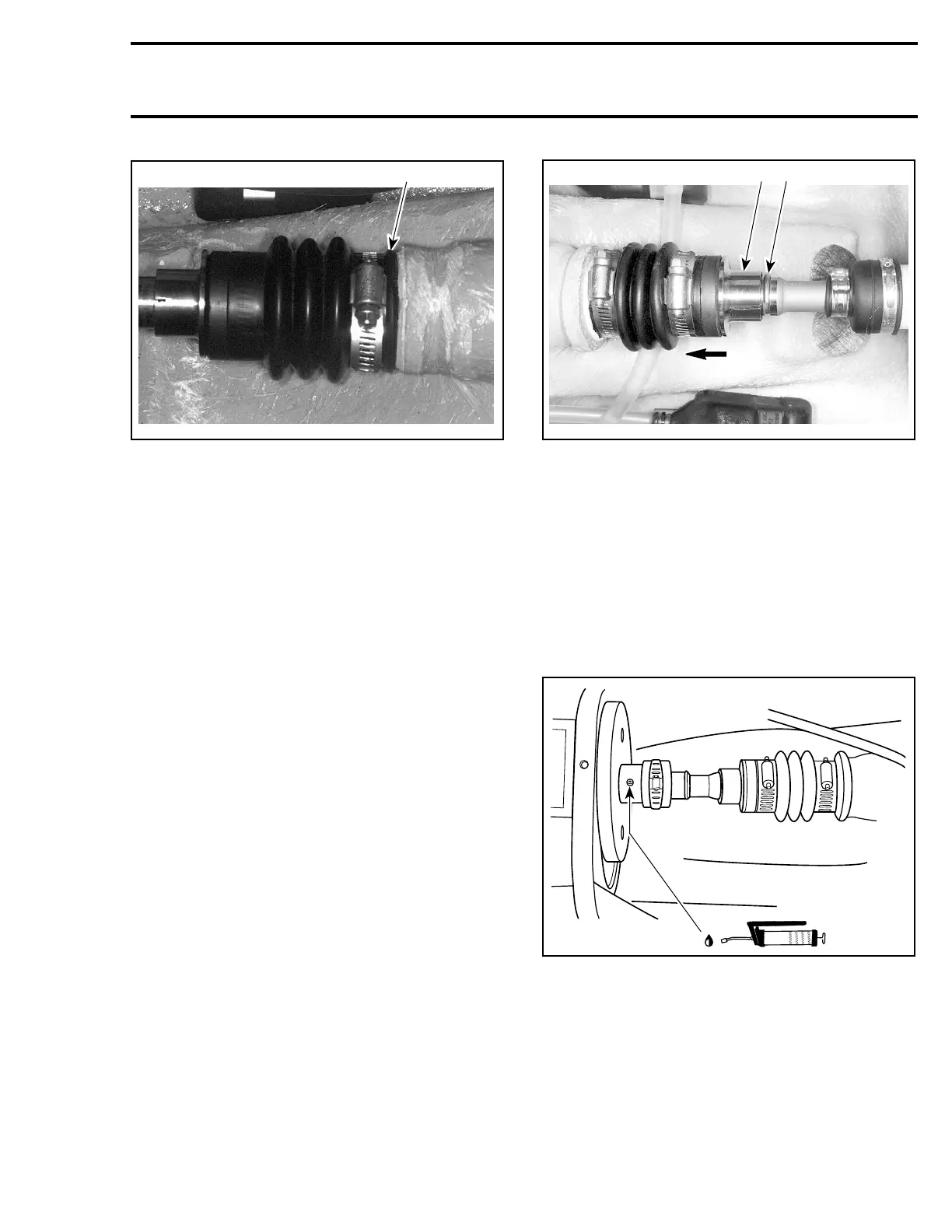
Circlip
Push the floating ring no. 6 to compress the boot
no. 7. Insert the circlip no. 8 in the drive shaft
groove.
F06I06A
1 2
1. Push floating ring
2. Insert circlip in the groove
Slide the floating ring onto the circlip.
LUBRICATION
PTO Flywheel
Using a grease gun, carefully lubricate PTO fly-
wheel with synthetic grease (P/N 293 550 010),
until boot no. 2 is just beginning to expand. At
this point, immediately stop greasing.
F01I0BB
smr2005-063 257