Section 11 HULL/BODY
Subsection 01 (GTI SERIES)
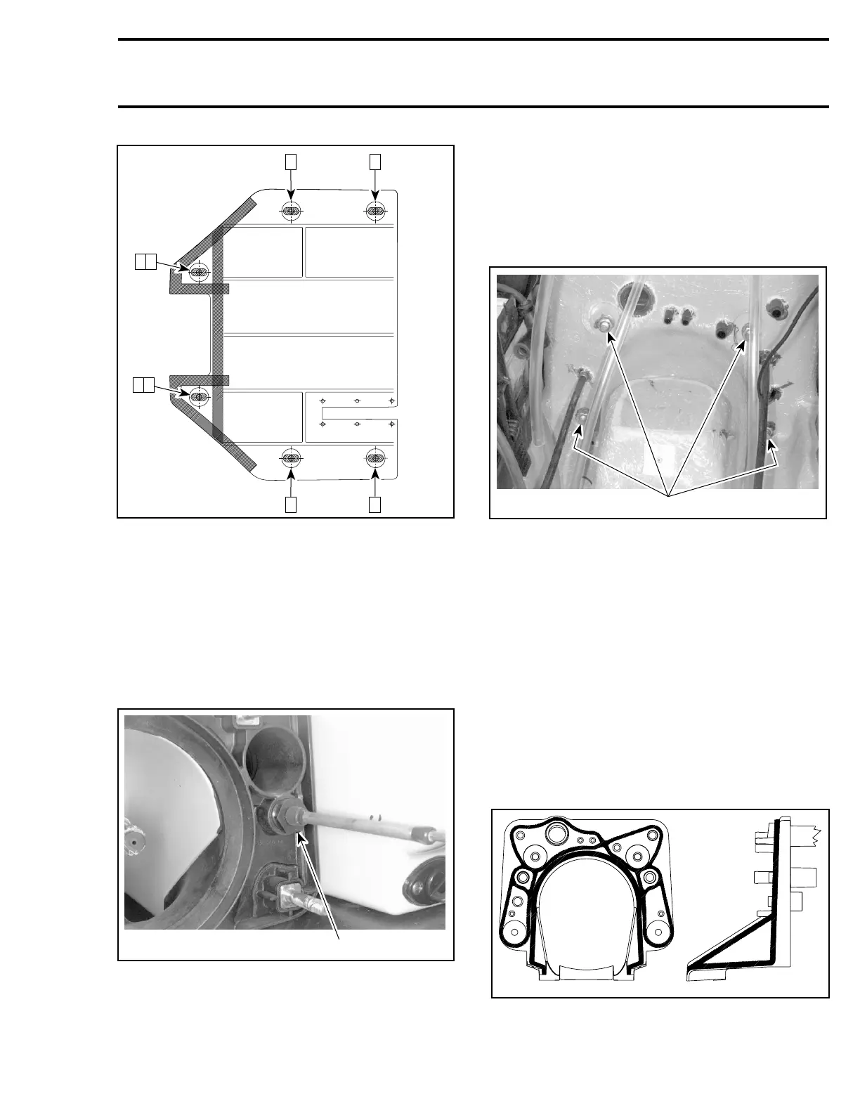
F08L1TA
6 4
8 2
7 1
5
3
Install all removed parts.
JETPUMPSUPPORT
Removal
Remove jet pump. Refer to JET PUMP.
Remove inlet grate and riding plate.
Remove ball joint, boot, nut, half rings and O-rings
from steering cable.
F05K02A
1
TYPICAL
1. Unscrew nut
Remove ball joint, boot, nut, half rings and O-rings
from reverse cable.
Disconnect water supply hose, water return hose
and bailer hoses.
Remove nuts, lock washers and flat washers re-
taining jet pump support.
F07L0AA
1
TYPICAL
1. Remove nuts
Using a heat gun, heat jet pump support until it is
possible to pull it.
NOTE: Shims may have been installed between
support and body. Do not remove these shims,
otherwise jet pump alignment will be altered.
Installation
Ensure to position the longest threaded portion of
studs towards the jet pump. Apply Loctite 518
(P/N 293 800 038) against contact surface of studs
with jet pump support.
Apply Loctite 5900 (P/N 293 800 066) as indicated
by the shaded areas in the next illustrations.
smr2005-069-009
smr2005-069 325