Section09PROPULSION
Subsection 03 (REVERSE SYSTEM)
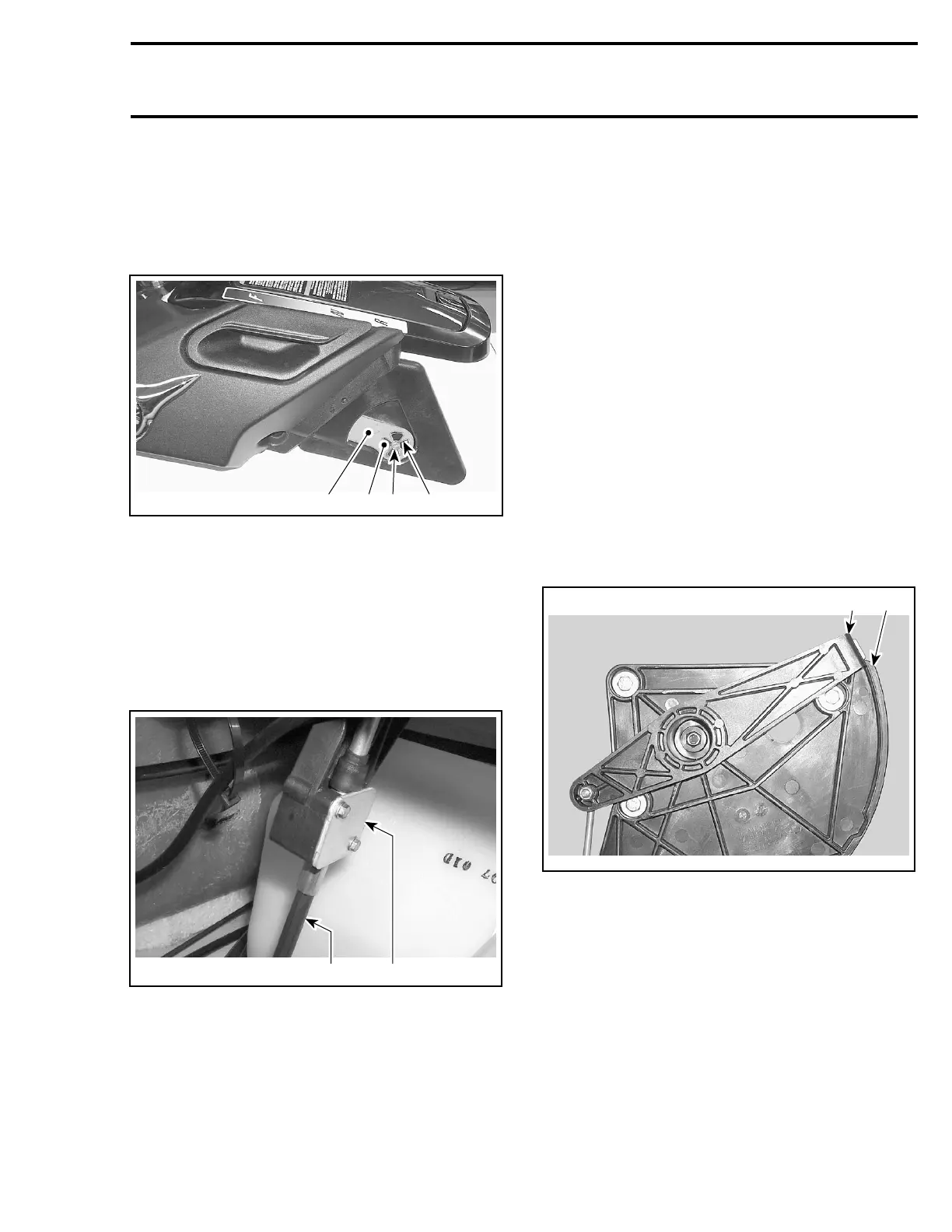
Shift Lever
Unscrew the shift lever retaining bolt no. 25,
washer and nut.
Disengage the shift lever slots from interior lever
tabs, then remove the shift lever no. 26.
4
F18J1KA
31 2
1. Shift lever retaining bolt
2. Shift lever slot
3. Interior lever tab
4. Shift lever
Reverse Cable Support
Remove:
– shift lever no. 26
– interior lever no. 21
– retaining bracket no. 24
2
F16J0FA
1
1. Bracket
2. Reverse cable
– bolts no. 27.
Withdraw reverse cable support no. 28.
Handle Housing
Remove:
– shift lever no. 26
– interior lever no. 21
– reverse cable support no. 28
– bolts no. 29.
Then, remove handle housing no. 30.
INSPECTION
Visually inspect parts for wear or cracks on friction
parts. Replace all defective parts.
ASSEMBLY
Assembly is essentially the reverse of disassem-
bly procedures. However pay particular attention
to the following.
Insert interior lever cursor into reverse cable sup-
port slider and make sure that the cursor slides
freely in the slider.
1
F18J1LA
2
1. Interior lever cursor
2. Reverse cable support slider
Interior Lever
Apply synthetic grease (P/N 293 550 010) on the
interior lever pivot and in the reverse cable support
hole.
Install the interior lever in a rotating movement.
Engage properly the interior lever tabs in the shift
lever slots.
smr2005-064 271