Section09PROPULSION
Subsection 01 (JET PUMP)
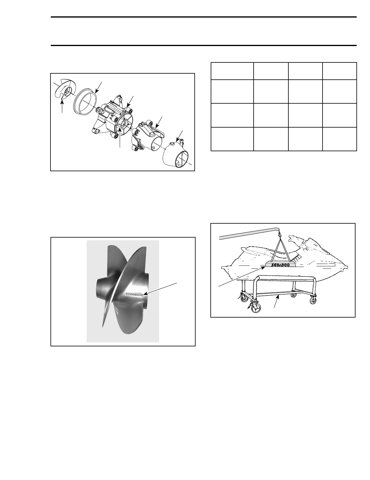
GENERAL
F00J0SA
5
2
1
6
3
4
1. Nozzle
2. Venturi
3. Jet pump housing
4. Wear ring
5. Impeller
6. Stator
Impeller Identification
To identify the impellers refer to the following il-
lustration and chart.
F02J0VA
1
1. Stamped part number
WATERCRAFT
MODEL
IMPELLER
P/N
MATERIAL PITCH
3D 267 000 201
Stainless
steel
Progressive
pitch
11° -20°
GTI 271 001 297
Stainless
steel
Progressive
pitch
10° -20°
GTI RFI,
GTI RFI LE
271 001 496
Stainless
steel
Progressive
pitch
11° -20°
JET PUMP INSPECTION ON
WATERCRAFT
To work on watercraft, securely install it on a
stand. Thus, if access is needed to water inlet
area, it will be easy to slide underneath watercraft.
A lift kit (P/N 295 100 206) can be used to install
watercraft on a stand.
F01J42A
1
2
TYPICAL
1. Lift kit
2. Work stand
Impeller Condition
Condition of impeller no. 1,bootno. 2 and wear
ring no. 3 can be quickly checked from underneath
of the watercraft. Using a flashlight, look through
water inlet.
Impeller/Wear Ring Clearance
This clearance is critical for jet pump performance.
To check clearance, remove jet pump from vehi-
cle. Refer further in this subsection for the com-
plete procedure.
smr2005-062 235