Section 09 PROPULSION
Subsection 02 (DRIVE SYSTEM)
F00J03A
1
A
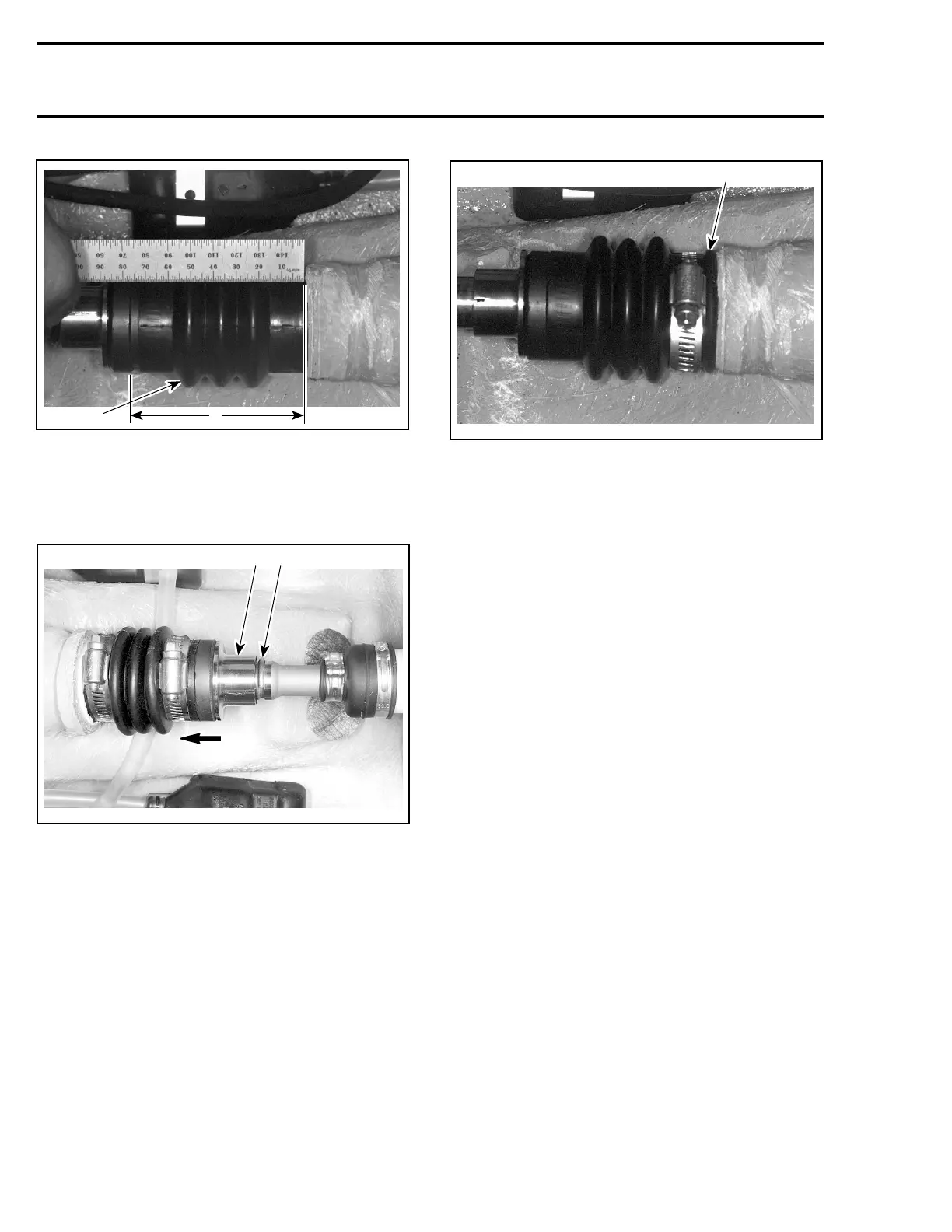
1. Boot
A. Measure here
Push floating ring no. 6 to compress boot no. 7;
then, remove circlip no. 8 out of drive shaft
groove.
F06I06A
1 2
1. Push floating ring
2. Remove circlip
Slide floating ring far enough forward in order to
release it from carbon ring no. 22.
Measure boot free length.
Subtract the installed length measurement from
the free length measurement. A difference of
4mmto12mm(5/32into15/32in)shouldbe
obtained.
If the length is less than 4 mm (5/32 in), install a
spacer (P/N 293 250 017) between boot and hull
fitting.
F00J04B
1
1. Spacer
NOTE: Drive shaft must be removed to install
spacer.
Seal Carrier of Mid Bearing
Inspect seal carrier needle bearing no. 17.Check
parts for scoring, pitting, chipping or other evi-
dence of wear.
Inspect seals no. 18 for deterioration or excessive
wear. Replace if necessary.
ASSEMBLY
Seal Carrier of Mid Bearing
Properly support seal carrier housing no. 14 when
installing seals no. 18 and bearing no. 17.
CAUTION: Ensure to install stamped end of
bearing (showing identification markings) first
on tool. Never hammer the bearing into its
housing.
Install bearing no. 17 with the bearing/seal in-
staller tool (P/N 295 000 107).
262 smr2005-063