Section09PROPULSION
Subsection 02 (DRIVE SYSTEM)
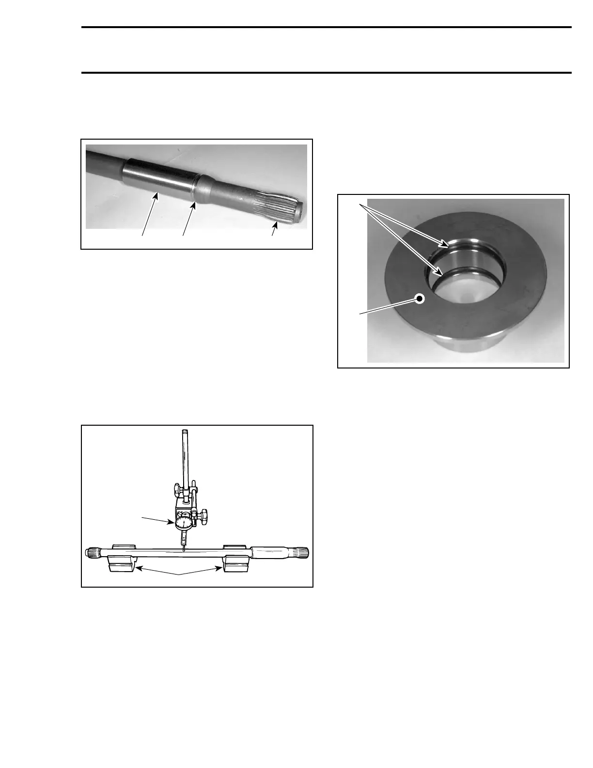
With your finger nail, feel machined surface of
drive shaft. If any irregular surface is found, re-
new drive shaft.
F01I0FA
321
TYPICAL
1. Surface condition
2. Groove condition
3. Splines condition
Excessive deflection could cause vibration and
damage to drive shaft splines, impeller, flywheel
or seal carrier.
Place rear drive shaft on V-blocks and set-up a dial
gauge in center of shaft. Slowly rotate shaft; dif-
ference between highest and lowest dial gauge
reading is deflection. Refer to the following illus-
tration.
Maximum permissible deflection is 0.5 mm
(.020 in).
1
2
F01J15A
MEASURING DRIVE SHAFT DEFLECTION
1. Dial gauge
2. V-blocks
Front Drive Shaft
Check condition of front drive shaft no. 13.
Check condition of couplers.
Replace front drive shaft if necessary.
Damper
Visually inspect shape of damper no. 24 for defor-
mation or other damage.
Floating Ring and O-Ring
Inspect condition of O-rings no. 25 and contact
surface of floating ring no. 6.
F01I0GA
1
2
1. O-rings
2. Floating ring contact surface
Boot
Inspect the condition of boot no. 7.Ifthereisany
damage or evidence of wear, replace it.
To verify the preload of the boot no. 7, proceed as
follows:
NOTE: To verify the boot preload and free length,
jet pump and drive shaft must be installed.
Measure boot length when normally installed on
drive shaft. Ensure circlip no. 8 is properly in-
stalledintogroove.
smr2005-063 261