Section 03 ENGINE SYSTEM
Subsection 03 (REMOVAL AND INSTALLATION)
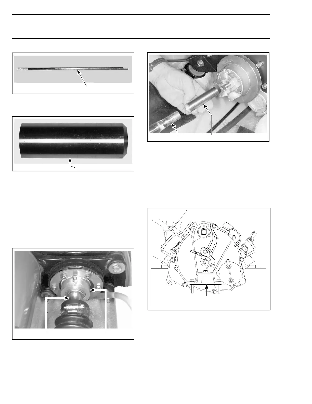
F00B0GA
1
1. Alignment shaft
– PTO flywheel adapter (P/N 529 035 590).
F00B11B
1
1. Adapter
Install support plate at rear of watercraft.
Install adapter on shaft.
NOTE: First ensure the mid bearing shaft support
has been properly aligned prior to performing en-
gine alignment. Refer to DRIVE SYSTEM. Then,
ensurethemidbearingisloosenedtochecken-
gine alignment.
Carefully slide alignment shaft through shaft sup-
port and seal carrier.
F05I08A
1 2
TYPICAL
1. Alignment tool
2. Seal carrier
1
F08I06A
2
1. Alignment shaft
2. Adapter
Continue to slide the alignment shaft forward and
install PTO adapter on shaft end.
If the alignment is incorrect loosen engine support
screws to enable to align PTO flywheel with shaft
end.
NOTE: Use shim(s)as necessary to correct align-
ment.
A
smr2005-049-005_a
787 RFI ENGINES — FRONT
68
smr2005-049