Section 07 ELECTRICAL SYSTEM
Subsection 03 (STARTING SYSTEM)
Check commutator for roughness, burnt or scored
surface. If necessary, turn commutator on a lathe,
enough to resurface only.
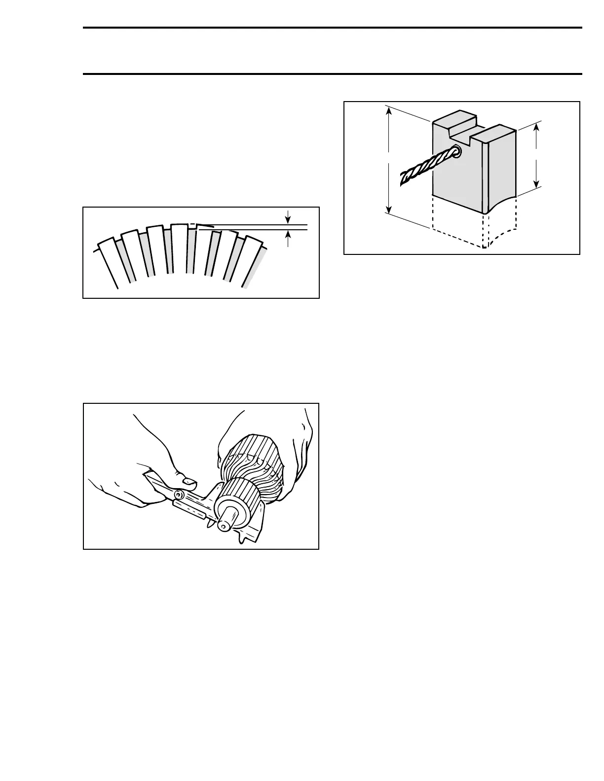
Check commutator for mica depth. If depth is less
than 0.20 mm (.008 in), undercut mica. Be sure
that no burrs are left and no copper dust remains
between segments after undercutting operation is
completed.
F01H0RA
1
1. Commutator undercut 0.20 mm (.008 in)
Check commutator out of round condition with
V-shaped blocks and an indicator. If commutator
out of round is more than 0.40 mm (.016 in), com-
mutator should be turned on a lathe.
Check commutator outer diameter. If less than
27 mm (1.063 in), replace.
A03E06A
Brush Holder
Check brush holder for insulation using an ohm-
meter. Place one test probe on insulated brush
holder and the other test probe on brush holder
plate. If continuity is found, brush holder has to
be repaired or replaced.
Brush
Measure brush length. If less t
han 8.5 mm
(.335 in), replace them.
NOTE: New brush length is 12 mm (.472 in).
A03E05A
1
2
1. New
2. Wear limit, 8.5 mm (.335 in)
Overrunning Clutch
Pinion of overrunning clutch should turn smooth-
ly in clockwise direction, and should not slip in a
counterclockwise direction. If defective, replace.
Check pinion teeth for wear and damage. If de-
fective, replace.
NOTE: Always check engine ring gear teeth for
wear and damage. If defective replace ring gear.
Refer to MAGNETO.
ASSEMBLY
Starter
Reverse the order of disassembly to reassemble
starter. However, attention should be paid to the
following operations.
Prior to assembling, coat sliding surfaces on arma-
ture shaft splines, overrunning clutch and bushing
(717 engines) with G.E. Versilube G 341 M or ES-
SO Beacon 325 lubricant or equivalent.
After placing pinion stop collar no. 7 on armature
shaft no. 11,fitcirclipno. 6 into armature shaft,
then make sure that it is properly secured.
Slidestopcollarno. 7 over circlip no. 6 and secure
in place by punching it at two or three places.
smr2005-059 191