Section 13 ELECTRICAL CONNECTORS AND WIRING DIAGRAMS
Subsection 01 (ELECTRICAL CONNECTORS)
Terminal Installation
For insertion of signal terminal, make sure the
wedge lock is in the open position.
NOTE: For insertion of power terminal, the wedge
lock may or may not be on the open position.
Insert terminal into appropriate circuit cavity and
push as far as it will go.
Pullbackontheterminalwiretobesurethereten-
tion fingers in the connector are holding the con-
tact properly.
After all required terminals have been inserted,
the wedge lock must be closed to its locked po-
sition.
Terminal Identification
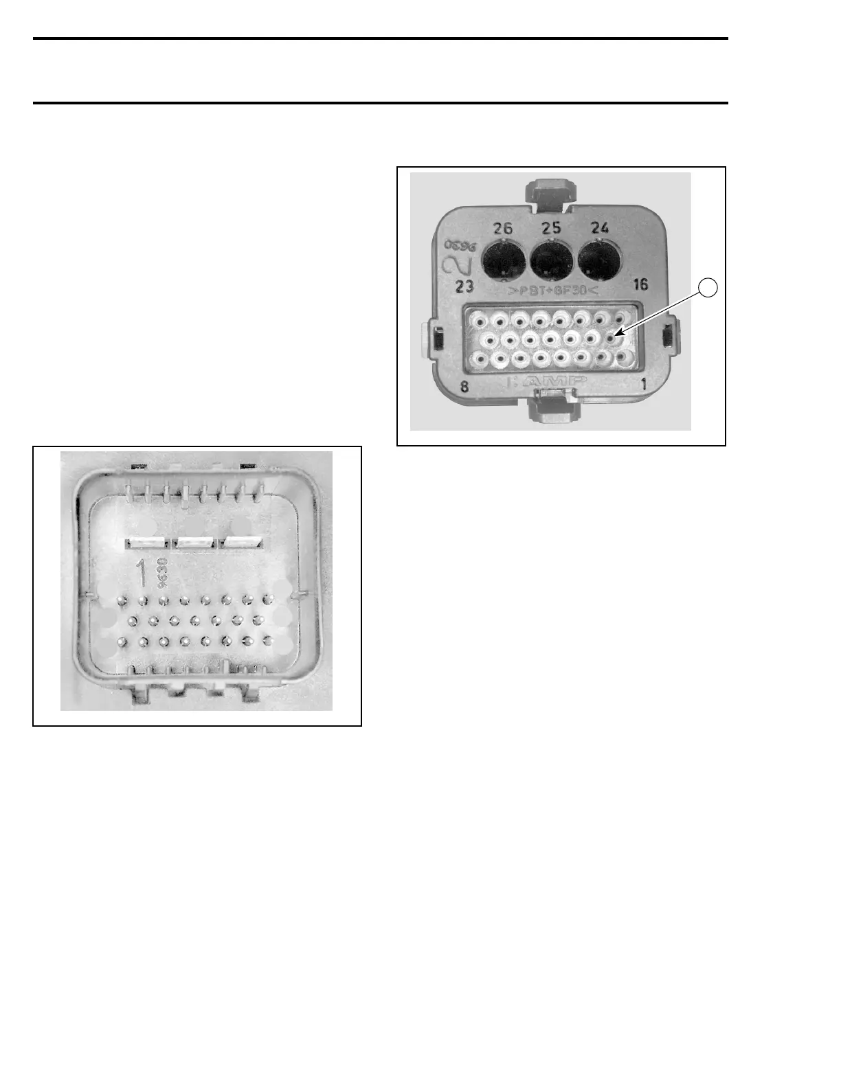
AMP Connectors of MPEM
26
25
24
23
15
8
16
9
1
F04H6RA
AMP Connectors of Wiring Harness
F04H6GA
9
ECM CONNECTORS
GTI Series with 787 RFI Engine
There are two ECM connectors used on the RFI
models and they are connected on the ECM. The
engine harness female connector is connected on
the module male connector “A” and the water-
craft system control harness female connector is
connected to the module male connector “B”.
The engine connector has 41 pins.
366 smr2005-073