Section 11 HULL/BODY
Subsection 02 (3D SERIES)
2
F00L2RA
3
3
1
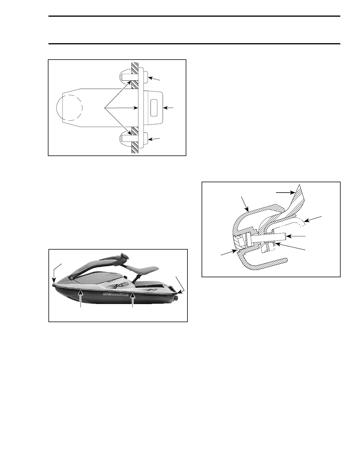
1. Drain plug
2. Silicone sealant
3. Torque screws to 2.2 N•m(19lbf•
in)
BUMPER
Removal and Installation
– Remove trim no. 9 from side bumper rail no. 10.
– Drill pop rivets no. 11 to remove side bumper
rail no. 10.
– Mark hole positions on body straight and bow
sections.
1
4 3
2
smr2005-069-021_a
TYPICAL
1. Front bumper
2. Corner bumper
3. Straight section
4. Bow section
– Slide bumper rail no. 10 under front bumper
no. 12.
– Using a 4.80 mm (3/16 in) drill bit, drill first hole
through bumper rail no. 10 at front of bow sec-
tion. Use locating mark as a guide. Then install
arivetno. 11.
CAUTION: When drilling, be careful not to
damage bumper rail and/or hull.
– Position bumper rail no. 10 properly onto body
and cut excess length if necessary.
– Slide bumper rail no. 10 in corner bumper
no. 13.
– Using hole positions previously marked on
body, drill holes in bumper rail no. 10 and install
rivets no. 11.
– Install trim no. 9 using soapy water.
– Repeat procedure for the other side.
When installing front bumper no. 12, note that
bumper screws are installed with a threaded in-
sert. The screws go through the deck and the
hull. Apply Loctite 243 (blue) (P/N 293 800 060) on
screw threads and torque to 2.5 N•m(22lbf•in).
1
5
6
3
4
2
smr2005-069-022_a
1. Front bumper
2. Cap
3. Screw
4. Threaded insert
5. Deck
6. Hull
SPONSON
NOTE: Removal and installation procedure for RH
and LH sponson is same.
Removal
Remove muffler or resonator. Refer to EXHAUST
SYSTEM.
From inside of hull, unscrew sponson nuts no. 14
then remove sponson no. 15.
smr2005-069 345