Section 11 HULL/BODY
Subsection 02 (3D SERIES)
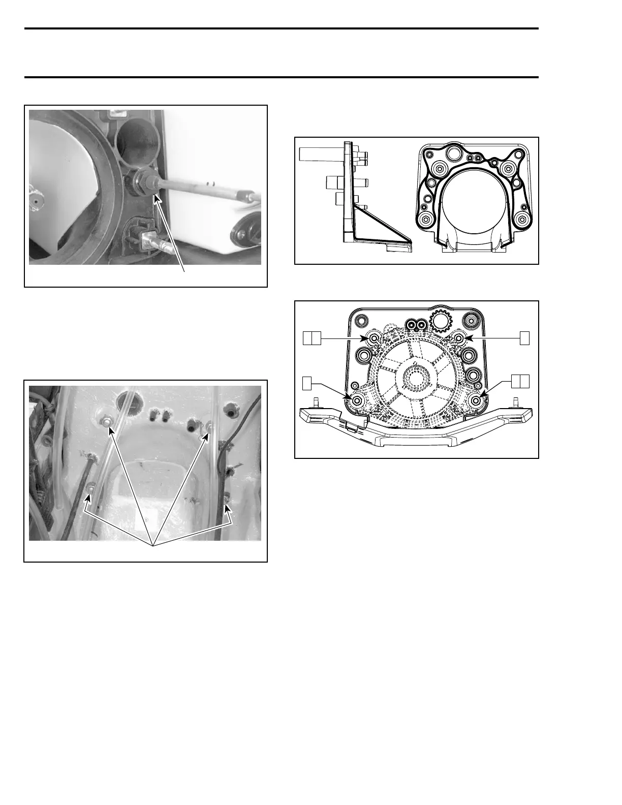
F05K02A
1
TYPICAL
1. Unscrew nut
Disconnect water supply hose, water return hose
and bailer hoses.
Remove nuts, lock washers and flat washers re-
taining jet pump support.
F07L0AA
1
TYPICAL
1. Remove nuts
Using a heat gun, heat jet pump support until it is
possible to pull it.
NOTE: Shims may have been installed between
support and body. Do not remove these shims,
otherwise jet pump alignment will be altered.
Installation
Ensure to position the longest threaded portion of
studs towards the jet pump. Apply Loctite 518
(P/N 293 800 038) against contact surface of studs
with jet pump support.
Apply Loctite 5900 (P/N 293 800 066) as indicated
by the shaded areas in the next illustrations.
smr2005-069-019
Torque nuts to 31 N•m(23lbf•ft) as per the fol-
lowing sequence.
15
4
62
3
smr2005-069-020_a
DRAIN PLUG
Installation
Before installation of drain plug no. 7, clean all
residues of old silicone sealant on hull and on drain
plug housing.
Apply silicone sealant (clear) (P/N 293 800 086) in
the screw holes.
Torque screws no. 8 to 2.2 N•m(19lbf•in).
From inside of bilge, apply silicone sealant (clear)
(P/N 293 800 086) around and on screws.
344 smr2005-069