Section 11 HULL/BODY
Subsection 02 (3D SERIES)
1
2
3 3
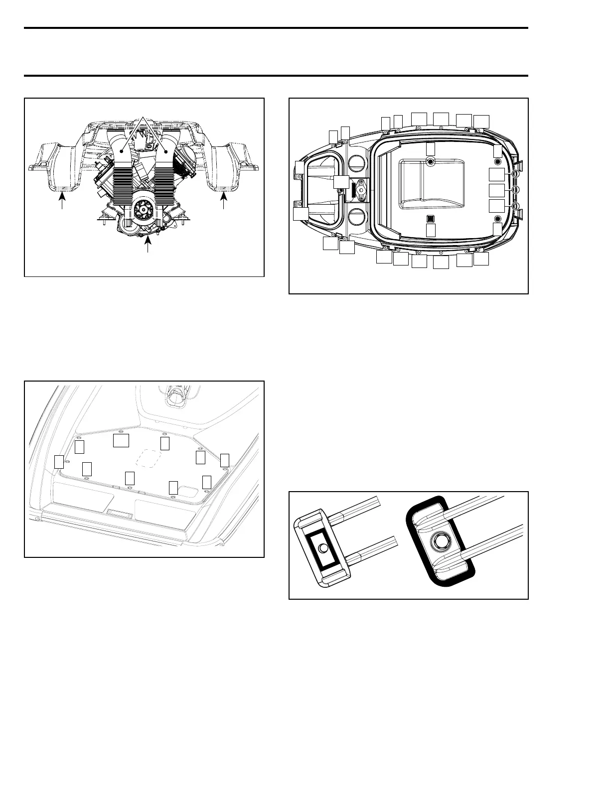
smr2005-069-016_a
1. Vent tubes in optimal position
2. Engine
3. Hull
REAR ACCESS COVER
When reinstalling cover no. 6, follow this tighten-
ing sequence.
1
10
5
3
7
2
9
6
4
8
smr2005-069-017_a
ENGINE COVER INNER SHELL
To remove inner shell, remove screws then using
a 3/16 drill, remove all rivets.
To assemble inner shell on engine cover it is im-
portant to use the following sequence.
5
26
6
7
8
9
10
11
12
13
2
24
23
25
4
22
3
21
20
19
18
17
16
15
14
1
smr2005-069-023_a
Step 1: Install screws, sequence 1 to 4
Step 2: Install rivets, sequence 5 to 26
INLET GRATE
Removal and Installation
Loosen screws and remove inlet grate.
NOTE: An impact screwdriver should be used to
loosen tight screws.
When reinstalling inlet grate, apply Loctite 271
(red) (P/N 293 800 005) on threads.
Apply Loctite 5900 (P/N 293 800 066) on the small
part of inlet grate as indicated by the shaded areas
in the next illustration.
smr2005-069-018
Follow this sequence referring to the illustration:
Hand tighten screws from 1 to 3.
Torquescrews1and2to11N•m(97lbf•in)then
retorque the first screw.
Torquescrew3to26N•m(19lbf•ft).
342 smr2005-069