Section 07 ELECTRICAL SYSTEM
Subsection 04 (INSTRUMENTS AND ACCESSORIES)
If there is no current supply to the electrical com-
ponents while the DESS switch and the cut-off re-
lay test good, check the wiring harness. If it tests
good, the MPEM could be suspected. Try a new
one.
INFORMATION CENTER
GTI LE RFI Models
FUNCTION WIRE
Tachometer signal
GRAY
Battery condition RED/FURPLE
Lake temp signal TAN/ORANGE
Speed sensor detection BLACK/RED
Maintenance signal BLACK/YELLOW
Lake temperature ground BLACK/ORANGE
Low oil signal BLUE
Fuel level signal PINK
Mode switch
YELLOW/PURPLE
Set switch GREEN/PURPLE
Switch supply PURPLE/ORANCE
High temperature signal TAN/BLUE
Power and speedometer
signal
PURPLE/YELLOW
Power supply (12Vdc) PURPLE
Ground BLACK
Compass North GREEN/WHITE
Compass West GREEN/RED
Compass South GREEN/YELLOW
Compass East GREEN/BLUE
Compass supply PURPLE/GREEN
Compass ground BLACK/GREEN
Exterior temperature ground
BLACK/WHITE
Exterior temperature signal TAN/WHITE
The accuracy of some features of the Information
Center can be checked with a potentiometer.
Fuel Level
Fuel Level Sender
Test fuel level sender. See FUEL LEVEL SENDER
further in this section. If sender works properly,
perform the following test.
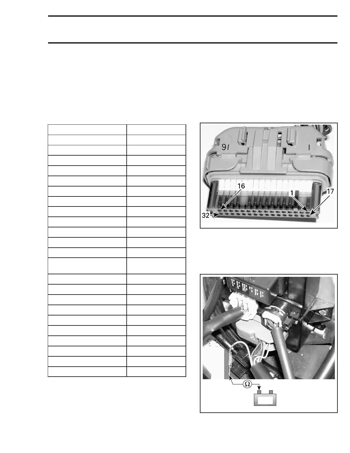
Fuel Level Input
Disconnect the connector #5 from the VCM.
smr2005-056-009_a
RemovethePINKwirefromposition21inthecon-
nector no. 5.
Reconnect the connector to VCM.
Connect potentiometer test probes between
PINK wire and battery ground.
-
+
BAT
smr2005-060-001_a
smr2005-060 201