Section 09 PROPULSION
Subsection 02 (DRIVE SYSTEM)
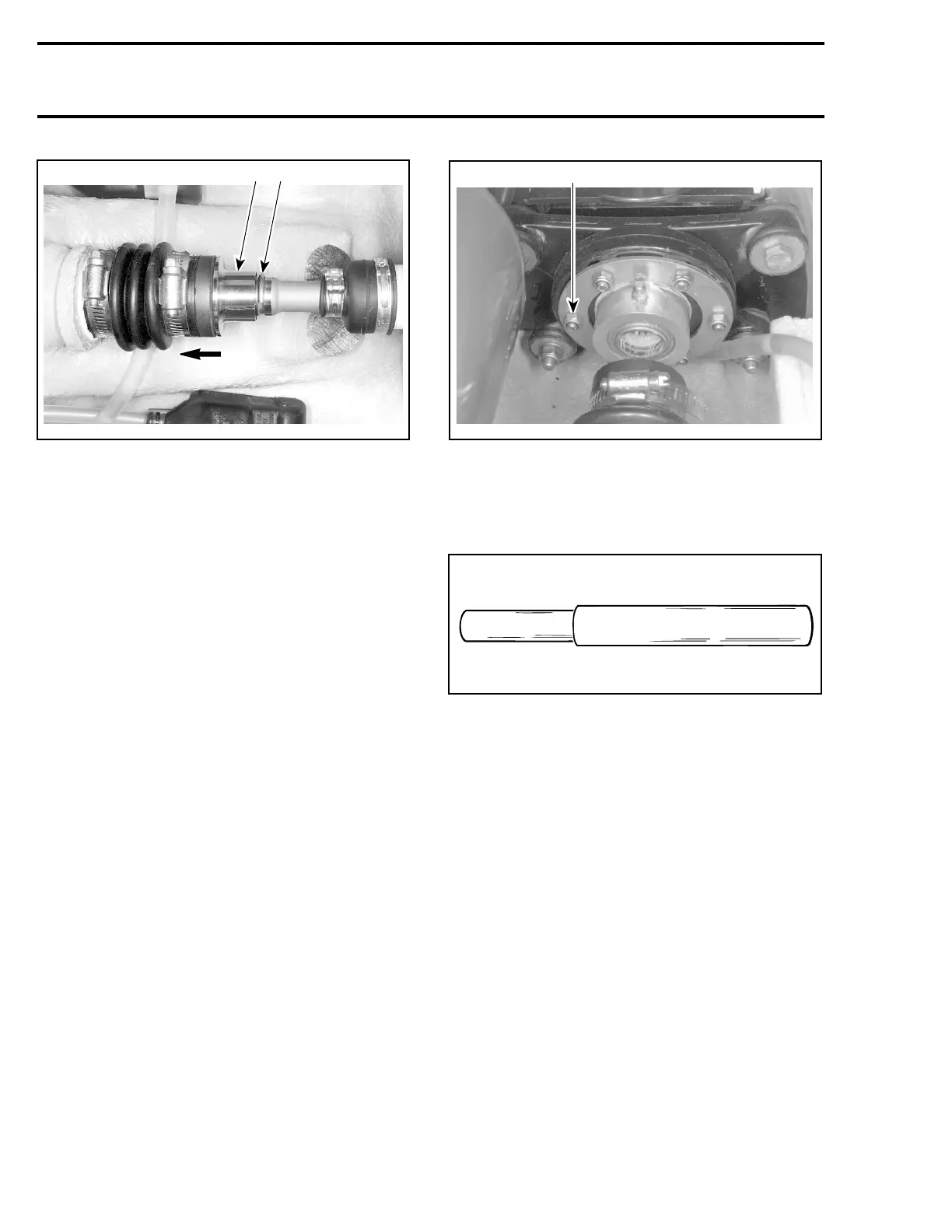
F06I06A
1 2
TYPICAL
1. Push floating ring
2. Remove circlip
Rear Drive Shaft
Remove rear access panel.
Remove circlip no. 8, see above.
Remove shaft guard no. 9.
Pull rear drive shaft no. 10 until shaft splines are
disengaged from coupler no. 11.
Remove rear drive shaft.
Remove coupler no. 11.
Front Drive Shaft
Remove PTO flywheel guard no. 2, rear drive shaft
no. 10, coupler no. 11 and deck support no. 12.
Pull front drive shaft no. 13 until its coupler is dis-
engaged from engine.
Remove front drive shaft.
Seal Carrier of Mid Bearing
To remove the seal carrier housing no. 14 from
support no. 15,loosenthe6nutsno. 16.
F05I05A
1
TYPICAL
1. Nut (6)
Bearing no. 17 and seals no. 18 can be easily
removed using the bearing/seal remover tool
(P/N 295 000 144).
F01J11A
NOTE: The same tool is used for bearing and seals
removal of jet pump.
Properly support seal carrier housing no. 14 when
removing seals and bearing.
Remove bushings no. 19 from alignment washer
no. 20.
Boot
Loosen gear clamp no. 21 holding boot no. 7,then
carefully pull boot and carbon ring no. 22 from hull
insert.
Carbon Ring
Loosen gear clamp no. 23 then pull carbon ring
no. 22 from boot no. 7.
INSPECTION
Rear Drive Shaft
Inspect condition of drive shaft no. 10 and splines.
Inspect condition of groove.
260 smr2005-063