Section 06 ENGINE MANAGEMENT (RFI)
Subsection 03 (COMPONENT ADJUSTMENT, INSPECTION AND REPLACEMENT)
Leakage Test
To perform a leakage test, the injectors and fu-
el rail have to be removed from engine. See RE-
MOVAL in this subsection for the procedure.
NOTE: Do not detach injectors from fuel rail.
Reconnect the wire connector of the injector.
Place each injector in a clean bowl.
Install the safety lanyard cap on the switch to ac-
tivate the fuel pump.
Check for fuel leakage from the injector nozzle.
There should be less than 1 drop of fuel per
minute.
2
1
F07F16A
3
1. Fuel injectors
2. Fuel rail
3. Injector nozzles
If not within specification, replace the fuel injec-
tor(s).
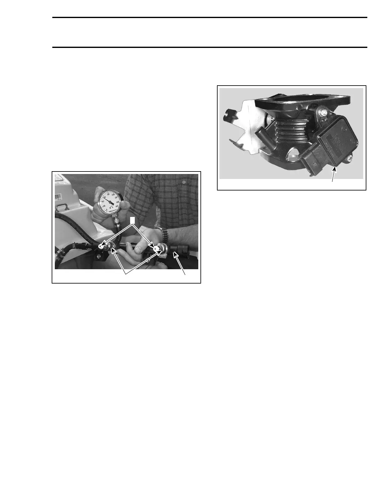
THROTTLE POSITION SENSOR
(TPS)
F07F0EA
1
1. TPS
IMPORTANT: Prior to testing the TPS, ensure that
mechanical components/adjustments of throttle
body are adequate.
The EMS may generate several fault codes per-
taining to the TPS. Refer to DIAGNOSTIC PROCE-
DURES section for more information.
Wear Test
While engine is not running, activate throttle and
pay attention for smooth operation without physi-
cal stops of the cable.
Using the vehicle communication kit (VCK) with
the B.U.D.S. software, use the Throttle Opening
display under Monitoring tab.
Slowly and regularly depress the throttle. Ob-
serve the needle movement. It must change
gradually and regularly as you move the throttle.
If the needle “sticks”, bounces, suddenly drops
or if any discrepancy between the throttle move-
ment and the needle movement is noticed, it
indicates a worn TPS that needs to be replaced.
Resistance Test
Ensure TPS is connected to wiring harness.
Disconnect the A connector from the ECM.
Using a multimeter, check resistance values on
ECM connector as per the following table.
smr2005-056 135