Section 09 PROPULSION
Subsection 02 (DRIVE SYSTEM)
Damper
Visually inspect shape of dampers no. 13 for de-
formation or other damage.
Floating Ring and O-Ring
Inspect condition of O-rings no. 14 and contact
surface of floating ring no. 6.
F01I0GA
1
2
1. O-rings
2. Floating ring contact surface
Boot
Inspect the condition of boot no. 7.Ifthereisany
damage or evidence of wear, replace it.
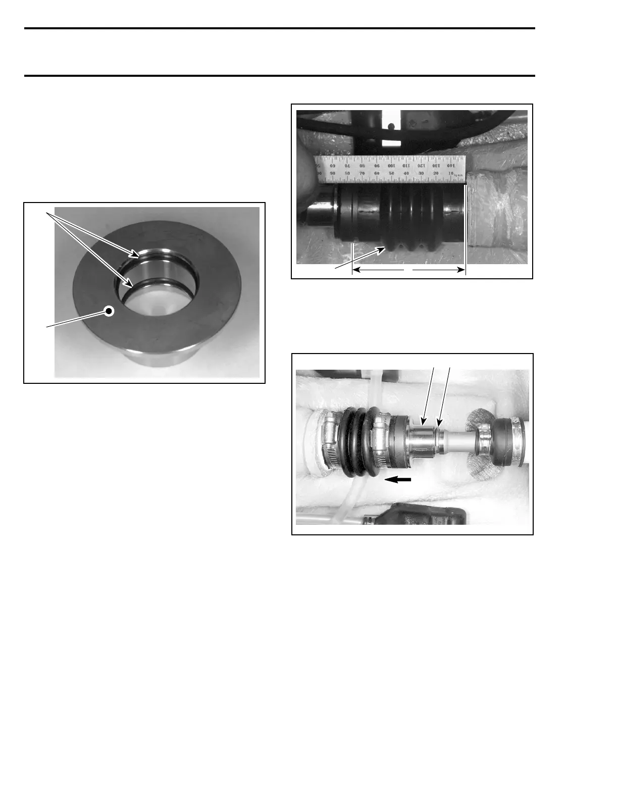
To verify the preload of the boot no. 7, proceed as
follows:
NOTE: To verify the boot preload and free length,
jet pump and drive shaft must be installed.
Measure boot length when normally installed on
drive shaft. Ensure circlip no. 8 is properly in-
stalledintogroove.
F00J03A
1
A
1. Boot
A. Measure here
Push floating ring no. 6 to compress boot no. 7;
then, remove circlip no. 8 out of drive shaft
groove.
F06I06A
1 2
1. Push floating ring
2. Remove circlip
Slidefloatingringfarenoughforwardinorderto
release it from carbon ring no. 11.
Measure boot free length.
Subtract the installed length measurement from
the free length measurement. A difference of
4mmto12mm(5/32into15/32in)shouldbe
obtained.
If the length is less than 4 mm (5/32 in), install a
spacer (P/N 293 250 017) between boot and hull
fitting.
256 smr2005-063