Section 07 ELECTRICAL SYSTEM
Subsection 01 (IGNITION SYSTEM)
A25E0RA
1
2
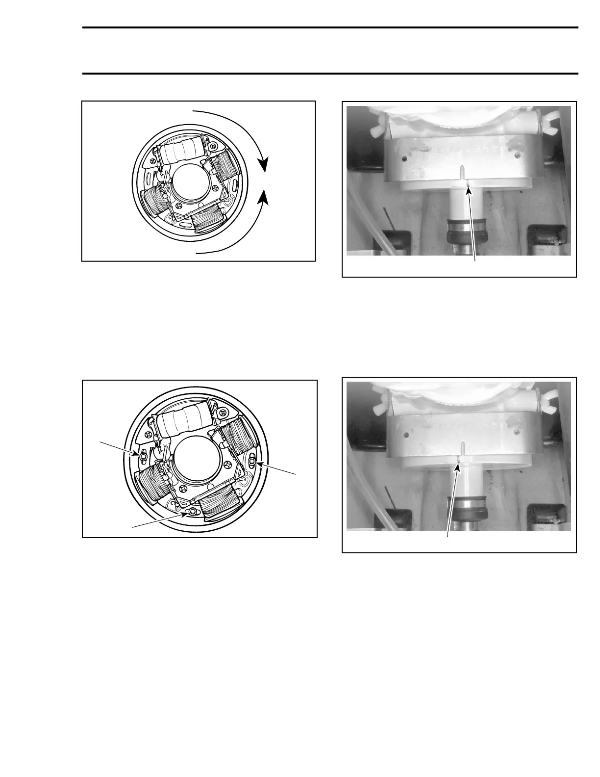
TYPICAL
1. To retard
2. To advance
To adjust, loosen 3 armature plate retaining
screws and slightly rotate armature plate in prop-
er direction.
NOTE: As a guideline, turn the armature plate the
sameamountneededtoalignmarkonPTOfly-
wheel.
A25E0VA
1
1
1
TYPICAL
1. Retaining screw
Example 1
When PTO flywheel mark is on right side of timing
tool slot, it indicates advanced timing.
F01H5UA
1
1. Too advanced timing
In this case, turn armature plate clockwise when
facing it.
Example 2
When PTO flywheel mark is on left side of timing
tool slot, it indicates retarded timing.
F01H5VA
1
1. Retarded timing
In this case, turn armature plate counterclockwise
when facing it.
After adjustment, tighten armature plate retaining
screws.
CAUTION: Armature plate screws must have
Loctite 243 (P/N 293 800 060) applied before
tightening. Make sure armature plate screws
are well secured.
Reinstall removed parts. Refer to MAGNETO
SYSTEM.
Recheck ignition timing (make sure engine is cold).
smr2005-057 149