Section 07 ELECTRICAL SYSTEM
Subsection 01 (IGNITION SYSTEM)
F01H5TA
1
TYPICAL
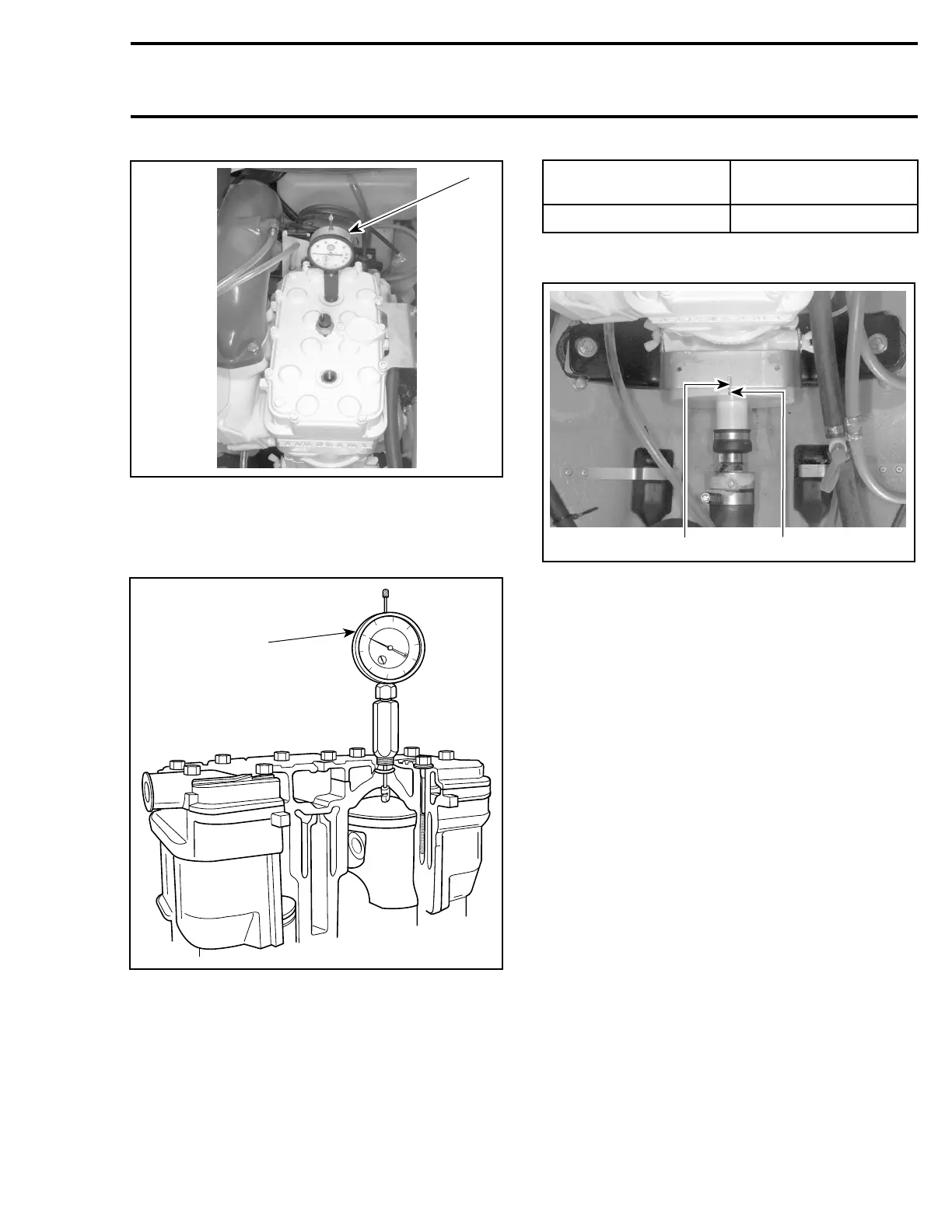
1. TDC gauge on MAG side
– Rotate PTO flywheel counterclockwise (when
facing it) until piston is at top dead center.
90
80
70
60
50
40
30
20
10
0
1
F01H4LA
TYPICAL
1. Adjust gauge dial at zero
– From this point, rotate flywheel clockwise to
reach proper specification according to engine.
Refer to the following chart.
ENGINE
IGNITION TIMING
(BTDC)
717
2.59 mm (.102 in)
– Scribe a thin mark on PTO flywheel in the mid-
dle of tool slot.
F01H5SB
1
2
TYPICAL
1. Tool slot
2. Flywheel mark
NOTE: This mark becomes the reference when
verifying the ignition timing (dynamic test).
– Remove TDC gauge.
– Reinstall spark plug and connect wire.
Ignition Timing Verification
(Dynamic Test)
To check ignition timing, use a timing light (avail-
able at local facilities).
NOTE: Ensure to use a timing light capable to
work with 2-stroke engines and rated up to 6000
RPM. Otherwise, an inaccurate reading will be ob-
tained.
The ignition components are affected by tempera-
ture variation, therefore, timing must be checked
when engine is cold, after idling for a MAXIMUM
of 20 seconds.
– Connect an induction-type tachometer (P/N 529
014 500) to spark plug wire.
smr2005-057 147