6PDUW/LQH0RGXOH
/LQH
FRQWDFWRU
/LQHUHDFWRU
/LQHILOWHU
0DLQVZLWFK
/('V
'&/,1.
5($'<
'2:DUQLQJ,W
'25HDG\
(39
(30
','LVDEOH
0
',5HVHW
9
&8
'2
9
&8
',
0
&8
'2
8:9
:9
;
8
&8
'2
&8
',
&8
',
0
H[W
9
0
;
;
;
3(
/
/
/
3(
/
/
/
'&3
'&1
0
&8
'2
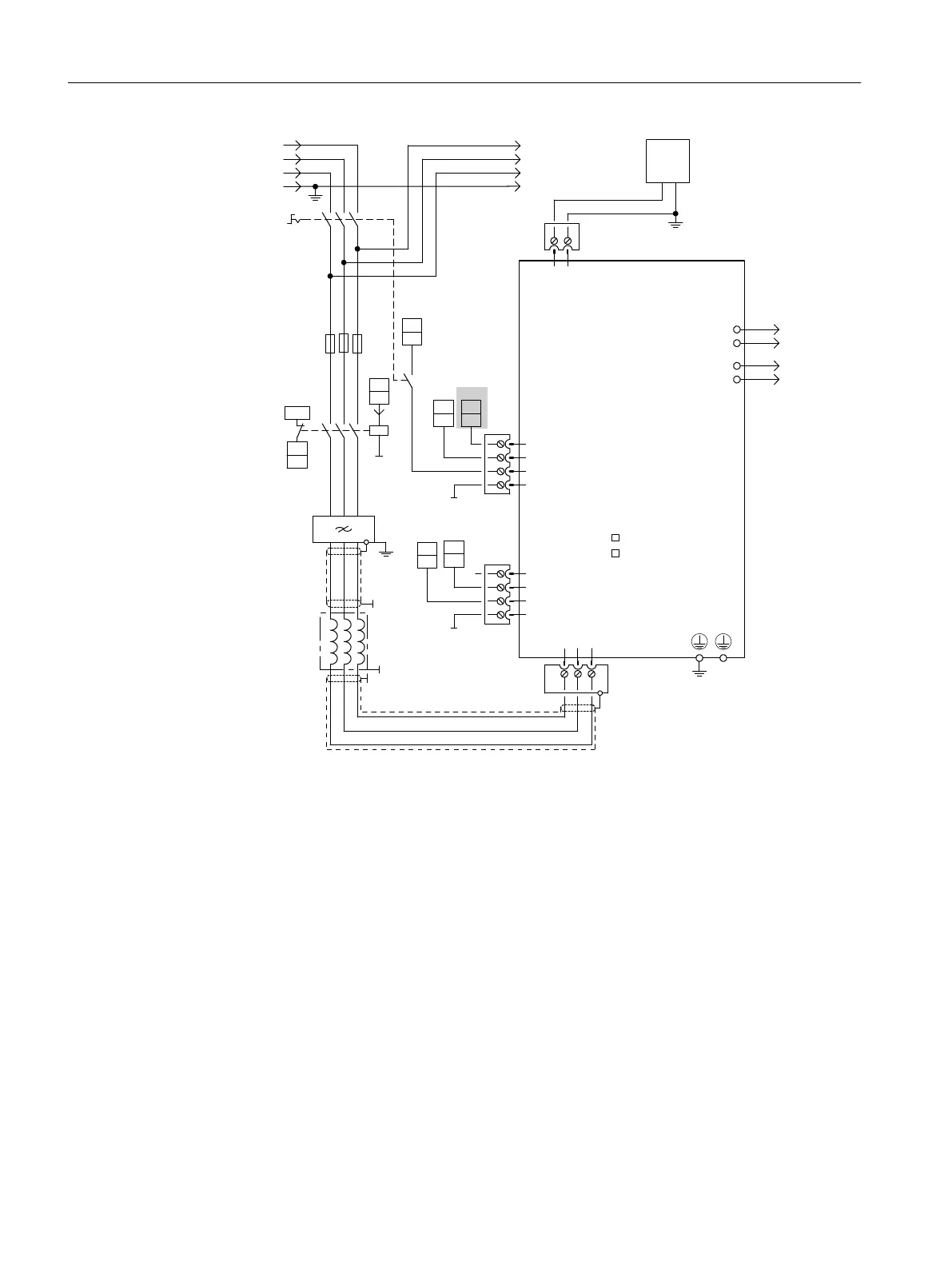
① Early opening contact t > 10 ms, 24 VDC and ground must be applied for operation
② DI/DO controlled by the Control Unit
③ No additional load permitted downstream of line contactor
④ The current carrying capacity of the DO must be observed; an output interface must be used if
required.
⑤ DO high, feedback deactivated (a jumper can be inserted between X22 pin 1 and pin 2 for
permanent deactivation).
⑥ X22 pin 4 must be connected to ground (external 24 V).
⑦ Contacting via rear mounting panel or shielding buses in accordance with EMC installation
guideline
⑧ 5 kW and 10 kW line filters via shield connection
⑨ Signal output of the control, to avoid interference of the 24 VDC supply on the EP terminal.
⑩ Connect via BICO to parameter p0864 → X122.1
Figure 5-21 Example: SLM connection
ON/OFF1 enable: Connection of Smart Line Module pin X21.1 → X122.1 SINUMERIK 828D
Commissioning the drive
5.5 Terminal assignments
CNC commissioning
150 Commissioning Manual, 10/2015, 6FC5397-3DP40-5BA3

 Loading...


