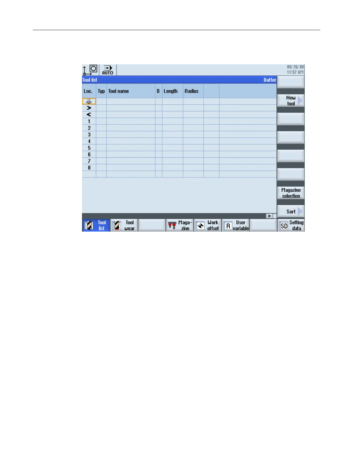
Display in operating software
Figure 9-7 Tool list Milling machine
9.8.2
Flow chart: Tool change
Tool change program sequence (PLC)
The sequence described here describes the change between magazine and spindle. The
changing
of
manual
tools as well as loading and unloading are not taken into account. These
sequences are described in:
● Example: Loading/unloading (Page 298)
● Example: Change manual tools (Page 300)
The machine data default setting is selected such that the job for "Prepare tool change" is
triggered with the T command on the interface:
N10 T = "Tool name" M6
The block preprocessing is not interrupted. M6 is used to start the tool change subprogram
(L6) at the same time. As soon as the job for "Prepare tool change" has been acknowledged
and in the tool change subprogram the M code for tool change output has been reached, the
"Execute tool change" job is output to the interface (block splitting).
Tool management
9.8 Application example for milling machine
CNC commissioning
Commissioning Manual, 10/2015, 6FC5397-3DP40-5BA3 321

 Loading...


