7.9.3 Measuring in the JOG mode
Preconditions
You have already made the settings from the previous section "Measuring cycles and
measurement functions, general (Page 170)".
Workpiece measurement
For milling:
●
The probe has been inserted in the tool spindle.
● The probe has been selected in the tool list as type 7xx (probe).
● The probe is activated as tool in the current NC channel.
Tool measurement
To measure tools, an appropriate probe must be located in the machine space so that this can
be reliably and safely reached with a tool in the spindle.
The following tool types are supported with the tool measurement:
● Milling technology: Tool types 1xx and 2xx
● Turning technology: Tool type 5xx, 1xx, 2xx
For the specified tool types, the tool lengths and the tool radii can be measured.
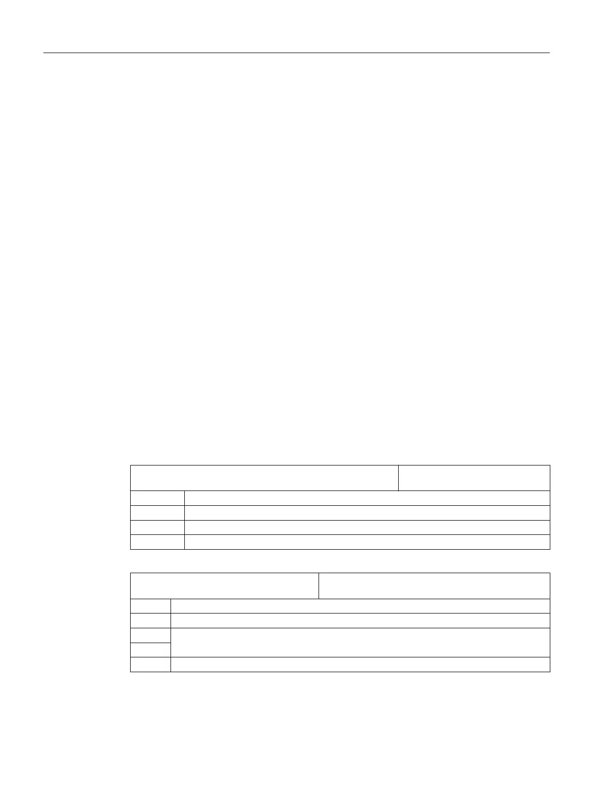
Setting general data
SD54782 $SNS_J_MEA_FUNCTION_MASK_TOOL Settings for the Tool measurement
in JOG input mask
Bit 2 Activates the "Enable automatic tool measuring" function.
Bit 3 Selects the tool probe calibration data field, enable.
Bit 10 Selects the individual cutting edge measurement
Bit 11 Selects spindle reversal when calibrating in the plane
MD51784 $MNS_J_MEA_T_PROBE_APPR
_AX_DIR [i]
Measuring in JOG: Approach direction in the plane to
the tool probe
-2 Negative direction, 2nd measuring axis
-1 Negative direction, 1st measuring axis (default setting)
0
Positive direction, 1st measuring axis
1
2 Positive direction, 2nd measuring axis
Configuring cycles
7.9 Measuring cycles and measurement functions
SINUMERIK Operate
176 Commissioning Manual, 10/2015, 6FC5397-3DP40-5BA3

 Loading...


