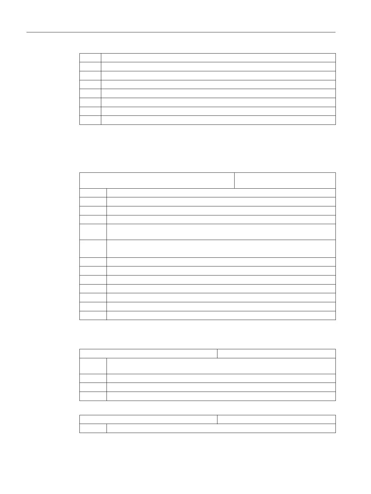
= 5 Counterspindle (turning)
= 6 Separate C axis of the counterspindle (turning)
= 7 Linear axis of the counterspindle (turning)
= 8 Tailstock (turning)
= 9 Steady (turning)
= 10 B axis (turning)
= 12 B axis in counterspindle (turning)
= 13 Transverse travel X of the counterspindle (turning)
Defining the direction of rotation
Enter the direction of
rotation for the rotary axes that are not configured in a tool holder or a 5-
axis transformation via the following channel-specific machine data.
MD52207 $MCS_USAGE_ATTRIB[n] Attribute of the axes in the channel
[n] channel axis number
Bit 0 Rotation around the 1st geometry axis (for rotary axes)
Bit 1 Rotation around the 2nd geometry axis (for rotary axes)
Bit 2 Rotation around the 3rd geometry axis (for rotary axes)
Bit 3 Direction of rotation is counter-clockwise (for rotary axis / C axis).
Bit 4 Displayed direction of rotation of the spindle / C axis for the M function M3 is counter-clock‐
wise
Bit 5 Inverts M3 / M4 (for spindles)
You must set this bit as for PLC bit DB38xx.DBX2001.6.
Bit 6 Display rotary axis as offset target for measurement
Bit 7 Offer rotary axis in the position pattern
Bit 8 Offer rotary axis to accept blank (on milling machines)
Bit 9 Spindle is not SPOS-capable
Bit 10 Rotary axis rotates around 1st geometry axis (only for position pattern)
Bit 11 Rotary axis rotates around 2nd geometry axis (only for position pattern)
Bit 12 Rotary axis rotates around 3rd geometry axis (only for position pattern)
Additional settings
MD52005 $MCS_DISP_PLANE_MILL PlaneSelectionMill
= 0 Plane selection in the operator interface (cycle support for programming under "program‐
GUIDE G-Code")
= 17 G17 plane (default value)
= 18 G18 plane
= 19 G19 plane
MD52006 $MCS_DISP_PLANE_TURN Plane selection turning
= 17 G17 plane
Configuring cycles
7.1 Activating turning/milling/drilling/grinding technologies
SINUMERIK Operate
78 Commissioning Manual, 10/2015, 6FC5397-3DP40-5BA3

 Loading...


