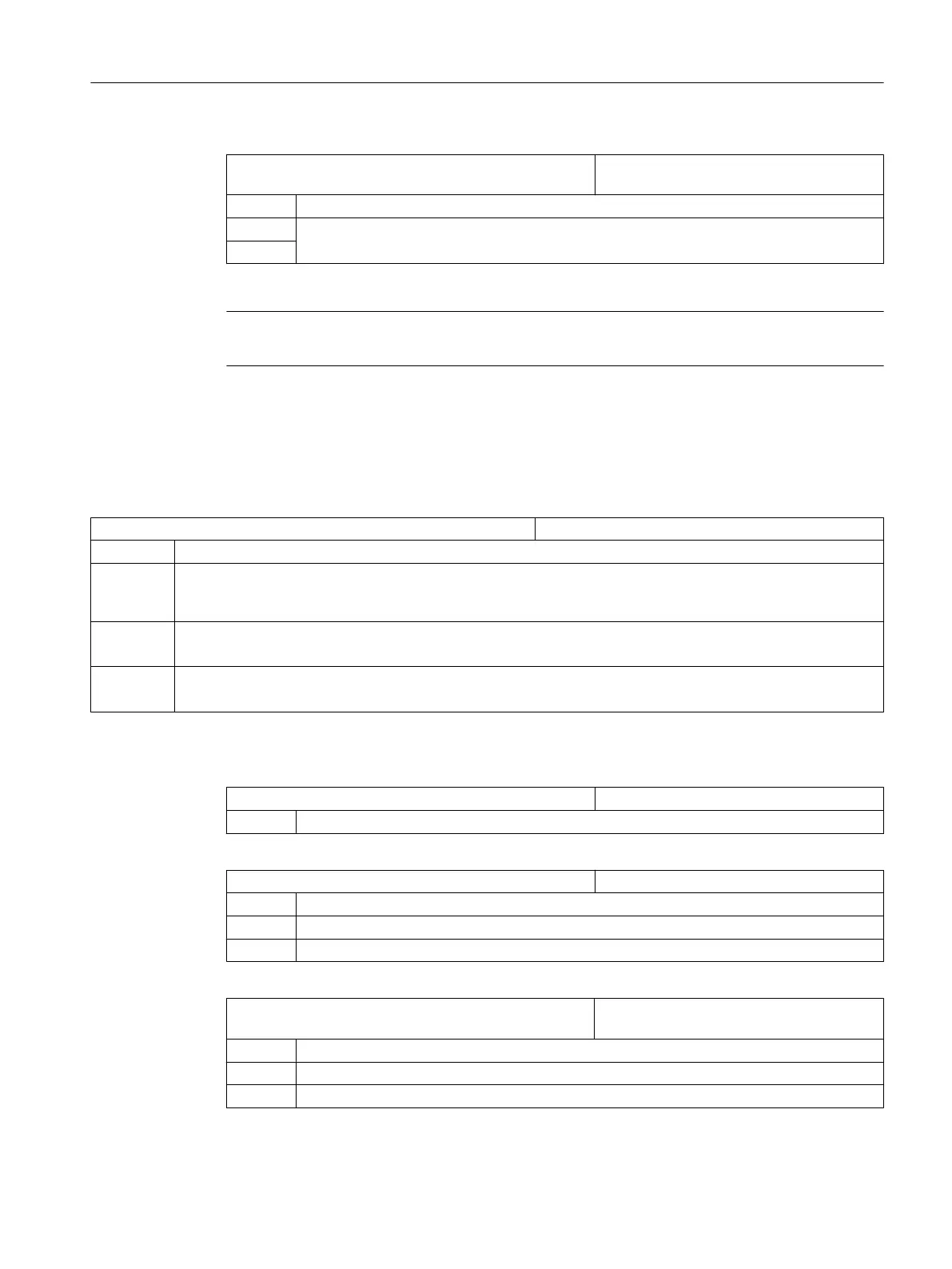
MD24400 $MC_TRAFO_TYPE_4 Cylinder surface transformation, counter‐
spindle: Transformation 4
= 512 without groove wall correction (without Y1 axis)
= 513 with groove wall correction (with Y1 axis)
with groove wall correction and Y1 correction
= 514
Note
You must also set up other machine data for each of the individual transformations.
Setting up cylinder surface transformation under ShopTurn
In addition, set the following channel-specific configuration machine data:
MD52214 $MC_FUNCTION_MASK_MILL Milling function screen
Bit 3 Enable "inside/rear" machining in ShopTurn screens which define the machining plane themselves.
Bit 4 If you have implemented the "Clamp/release spindle" function by means of the machine manufacturer cycle
CUST_TECHCYC.SPF, you can activate the "Clamp/release spindle" parameter in the drilling and milling
screens with this machine data.
= 0 The "Clamp/release spindle" parameter is not displayed in the drilling and milling masks.
ShopTurn automatically clamps the spindle if it makes sense for the particular machining operation.
=1 The "Clamp/release spindle" parameter is displayed in the drilling and milling masks.
The operator decides for which machining operation the spindle should be clamped.
Cylinder surface transformation without groove side offset
MD24300 $MC_TRAFO_TYPE_3 Definition of 3rd transformation in channel
= 512 TRACYL main spindle.
MD24310 $MC_TRAFO_AXES_IN_3[ ] Axis assignment for transformation 3
[0] = 1 Perpendicular to the rotary axis X1
[1] = 3 Rotary axis (main spindle) C1
[2] = 2 Parallel to the rotary axis Z1
MD24320 $MC_TRAFO_GEOAX_ASSIGN_TAB_3[ ] Assignment of the geometry axes to chan‐
nel axes for transformation 3.
[0] = 1 1st channel axis X1
[1] = 3 2nd channel axis Y1
[2] = 2 3rd channel axis Z1
Configuring cycles
7.5 Turning
SINUMERIK Operate
Commissioning Manual, 10/2015, 6FC5397-3DP40-5BA3 123

 Loading...


