Kinematics Swivel head HEAD_1
Direction reference Rotary axis 2
Correct tool No
Rotary axes
Rotary axis 1 C Mode Manual
Angular range 0.000 360.000
Rotary axis 2 A Mode Manual
Angular range -15.000 100.000
Example 2: Swivel head 2 "HEAD_2"
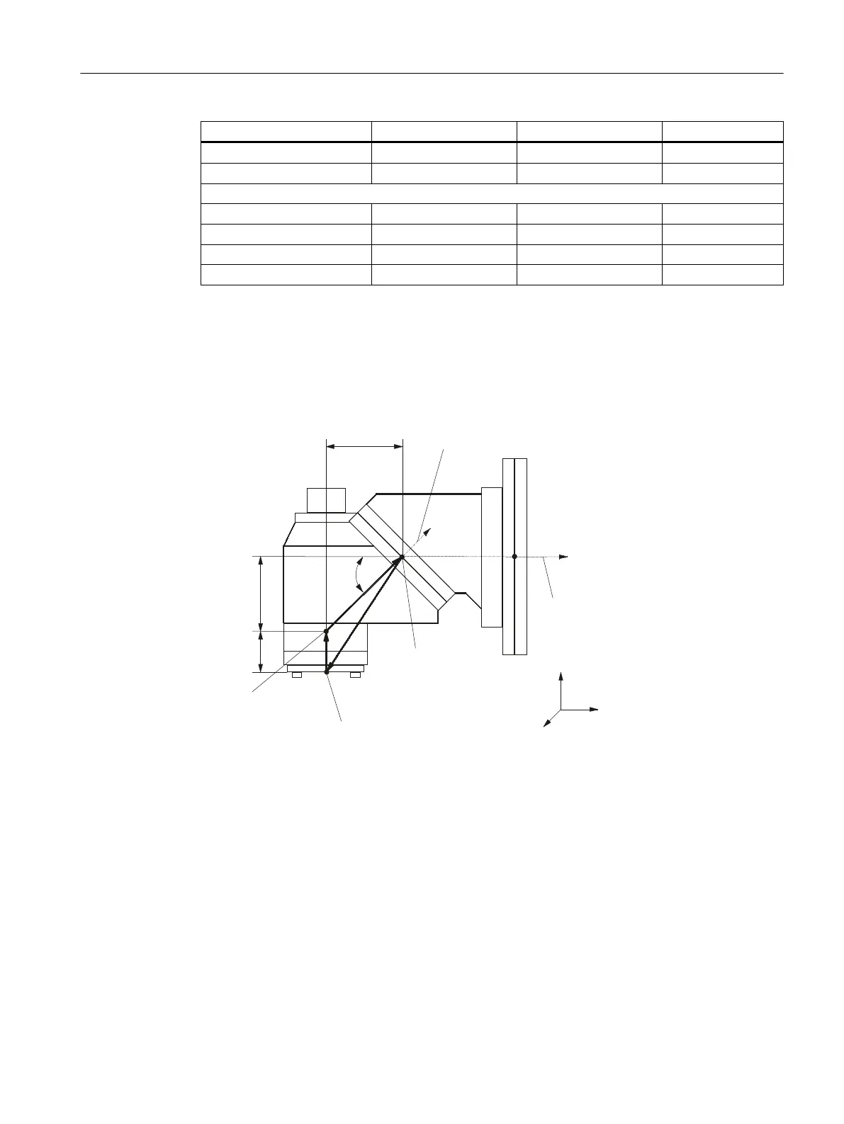
The vectors in the drawing refer to the initial setting of the kinematics. If the swivel head is
fixed-mounted, the vector chain
is closed. The reference point of the center of rotation of rotary
axes 1 and 2 can be offset on the line of rotation and does not have to coincide with the
mechanical center of rotation.
5RWDU\D[LV
&HQWHURIURWDWLRQRI
URWDU\D[LV
5RWDU\D[LV
&HQWHURIURWDWLRQ
RIURWDU\D[LV
5HIHUHQFHSRLQW
RIWRRO
9
9
JUG
,
,
,
;
=
<
Rotary axis vector V1 Rotary axis 1 rotates about Y.
Rotary axis vector V2 Rotary axis 2 rotates about Y and about Z.
Offset vector I1 Closure of vector chain with fixed-mounted swivel head, I1 = - (I2 + I3).
Offset vector I2 The distance between the center of rotation of rotary axis 1 and center of
rotation of rotary axis 2
Offset vector I3 The distance between the reference point of the tool and the center of rotation
of rotary axis 2.
Figure 7-10 Cardanic swivel head with Hirth joint, manually adjustable
Configuring cycles
7.7 Swiveling
SINUMERIK Operate
Commissioning Manual, 10/2015, 6FC5397-3DP40-5BA3 151

 Loading...


