Note
Calibrate probe
If you have calibrated the tool probe in JOG mode, then the calibration data has already been
correctly entered in: SD54632 $SNS_MEA_TP_AX_DIR_AUTO_CAL[k]
You do not need to recalibrate the tool probe in the AUTOMATIC mode.
Index [k] stands for the number of the actual data field (probe number -1).
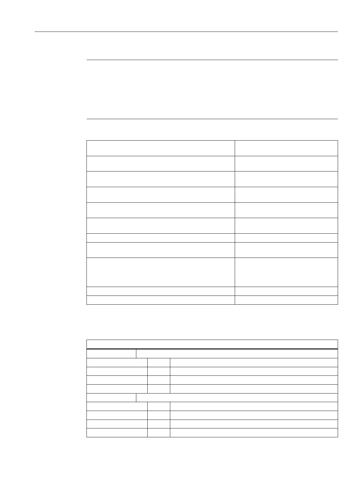
SD54625 $SNS_MEA_TP_TRIG_MINUS_DIR_AX1[k] Trigger point of the 1st measuring axis in
the negative direction.
SD54626 $SNS_MEA_TP_TRIG_PLUS_DIR_AX1[k] Trigger point of the 1st measuring axis in
the positive direction.
SD54627 $SNS_MEA_TP_TRIG_MINUS_DIR_AX2[k] Trigger point of the 2nd measuring axis
in the negative direction.
SD54628 $SNS_MEA_TP_TRIG_PLUS_DIR_AX2[k] Trigger point of the 2nd measuring axis
in the positive direction.
SD54629 $SNS_MEA_TP_TRIG_MINUS_DIR_AX3[k] Trigger point of the 3rd measuring axis in
the negative direction.
SD54630 $SNS_MEA_TP_TRIG_PLUS_DIR_AX3[k] Trigger point of the 3rd measuring axis in
the positive direction.
SD54631 $SNS_MEA_TP_EDGE_DISK_SIZE[k] Tool probe, edge length / disk diameter.
SD54632 $SNS_MEA_TP_AX_DIR_AUTO_CAL[k] Axes and directions for calibrating in AU‐
TOMATIC mode.
SD54634 $SNS_MEA_TP_CAL_MEASURE_DEPTH[k] Distance between the upper edge of the
tool
probe and lower
edge of the tool (cal‐
ibration depth, measuring depth for mill‐
ing radius).
SD54635 $SNS_MEA_TPW_STATUS_GEN[k] Calibration status
SD54636 $SNS_MEA_TPW_FEED[k] Measuring feedrate when calibrating
The general cycle setting data SD54632 $SNS_MEA_TP_AX_DIR_AUTO_CAL, is used to
define in which axes and directions it is possible to calibrate the tool probe.
Decimal place
ONES 1st axis
= 0 axis not possible
= 1 only minus direction
= 2 only plus direction
= 3 both directions
TENS 2nd axis
= 0 axis not possible
= 1 only minus direction
= 2 only plus direction
= 3 both directions
Configuring cycles
7.9 Measuring cycles and measurement functions
SINUMERIK Operate
Commissioning Manual, 10/2015, 6FC5397-3DP40-5BA3 193

 Loading...


