The current state values of the sensors, the tool clamping, the speed setpoint and the active
speed limitation are displayed in the signal overview
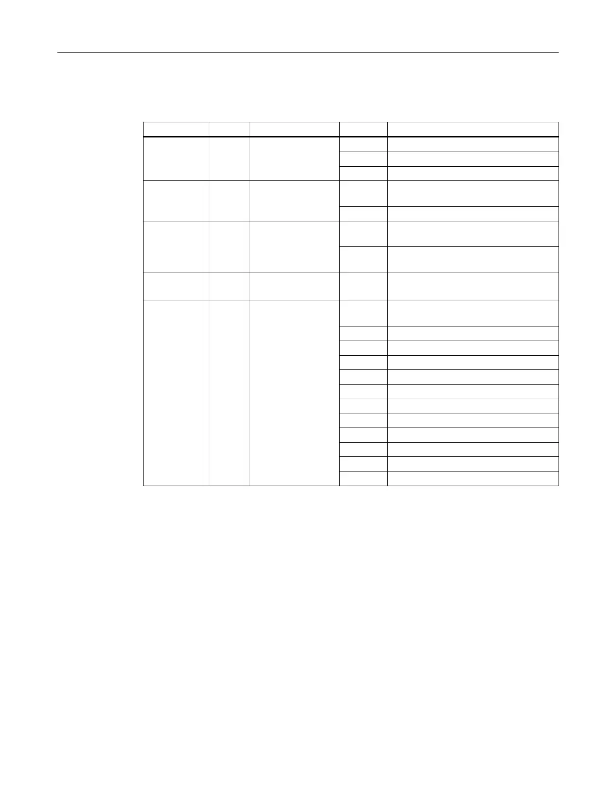
Signal Sensor Description Value Meaning
State S1 Clamping state 3 Released
7 or 8 Clamped with tool
10 Clamped without tool
Piston free S4 Plunger sensing Yes Release plunger not in contact with the
shaft.
No Release plunger in contact with the shaft.
Shaft in the
change posi‐
tion
S5 Position sensing Yes E.g. shaft is at a defined rotary angular
position.
No E.g. shaft is not at a defined rotary angu‐
lar position.
Speed set‐
point
Specification of the
speed
Speed specification by the user.
State Clamping states 0 Sensor S1 not available or state values
inactive.
1 The state initialization is in progress.
2 Released with signal (error state)
3 Released
4 Clamping with tool
5 Releasing with tool
6 Releasing without tool
7 Clamped with tool and S4 = 0 (No).
8 Clamped with tool and S4 = 1 (Yes).
9 Clamping without tool
10 Clamped without tool
11 Clamped with signal (error state)
State bar diagram
The clamping state is displayed by a state bar. The ranges shown in green indicate the state
ranges for "Clamped with or without tool" and "Tool released". The arrow marking indicates
the current analog sensor voltage of sensor S1.
For information on the associated interface signals (NC → PLC), refer to the following
documentation:
References
NC Variable and Interface
Signals List Manual, Section "Interface signals - Overview" > "Axis/
spindle-specific signals".
Spindle function
8.4 Spindle diagnostics
SINUMERIK Operate
Commissioning Manual, 10/2015, 6FC5397-3DP40-5BA3 215

 Loading...


