Advanced-control timers (TIM1/TIM8/TIM20) RM0440
1124/2126 RM0440 Rev 4
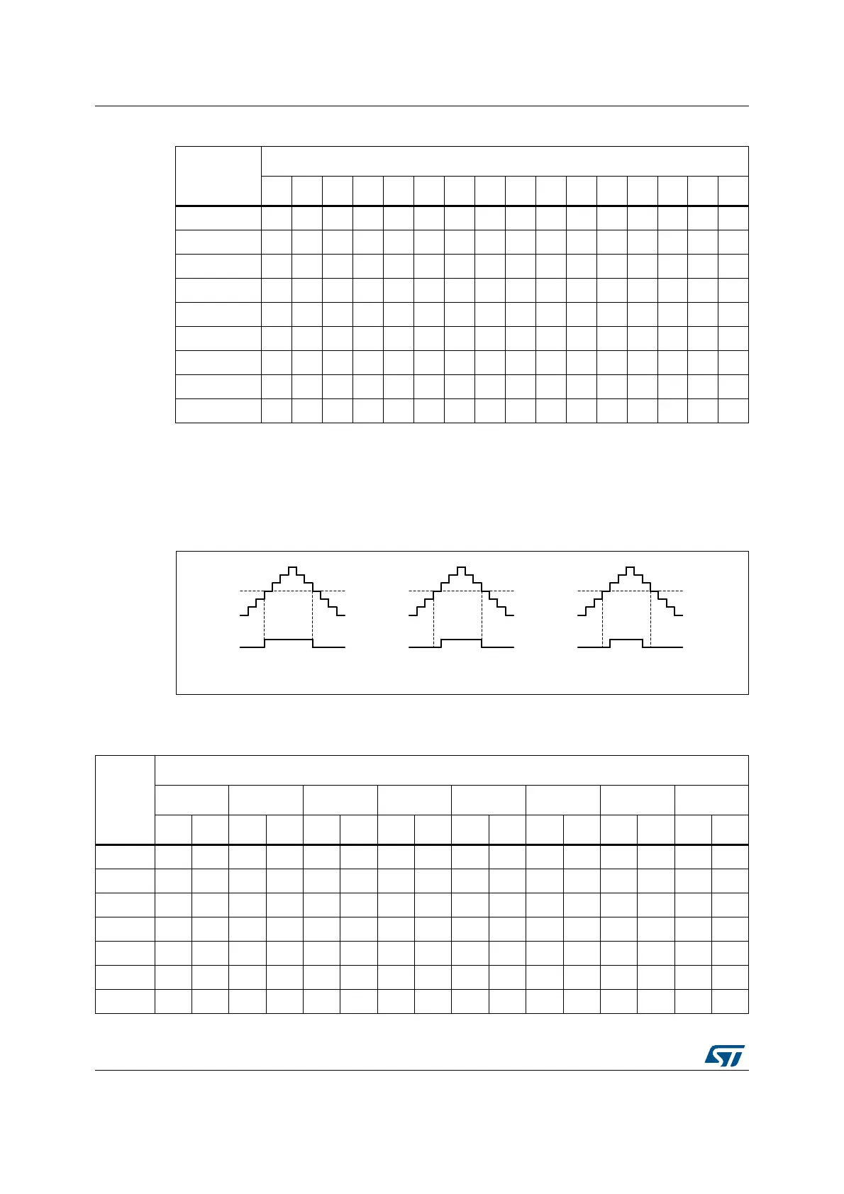
The dithering mode is also available in center-aligned PWM mode (CMS bits in TIMx_CR1
register are not equal to '00'). In this case, the dithering pattern is applied over 8 consecutive
PWM periods, considering the up and down counting phases as shown in the Figure 308
below.
Figure 308. Dithering effect on duty cycle in center-aligned PWM mode
Table 257 below shows how the dithering pattern is added in center-aligned PWM mode.
0111 +1 - +1 - +1 - +1 - +1 - +1 - +1 - - -
1000 +1-+1-+1-+1-+1-+1-+1-+1-
1001 +1+1+1 -+1 -+1 -+1 -+1 -+1 -+1 -
1010 +1 +1 +1 - +1 - +1 - +1 +1 +1 - +1 - +1 -
1011 +1+1+1 -+1+1+1 -+1+1+1 - +1 - +1 -
1100 +1 +1 +1 - +1 +1 +1 - +1 +1 +1 - +1 +1 +1 -
1101 +1 +1 +1 +1 +1 +1 +1 - +1 +1 +1 - +1 +1 +1 -
1110 +1+1+1+1+1+1+1 -+1+1+1+1+1+1+1 -
1111 +1 +1 +1 +1 +1 +1 +1 +1 +1 +1 +1 +1 +1 +1 +1 -
Table 256. CCR and ARR register change dithering pattern (continued)
LSB value
PWM period
12345678910111213141516
MSv50904V1
No dithering Dithering up Dithering down
Table 257. CCR register change dithering pattern in center-aligned PWM mode
LSB
value
PWM period
12345678
Up DnUpDnUpDnUpDnUpDnUpDnUpDnUpDn
0000 ----------------
0001 +1---------------
0010 +1-------+1-------
0011 +1---+1---+1-------
0100 +1---+1---+1---+1---
0101 +1-+1-+1---+1---+1---
0110 +1-+1-+1---+1-+1-+1---