RM0440 Rev 4 741/2126
RM0440 Digital-to-analog converter (DAC)
773
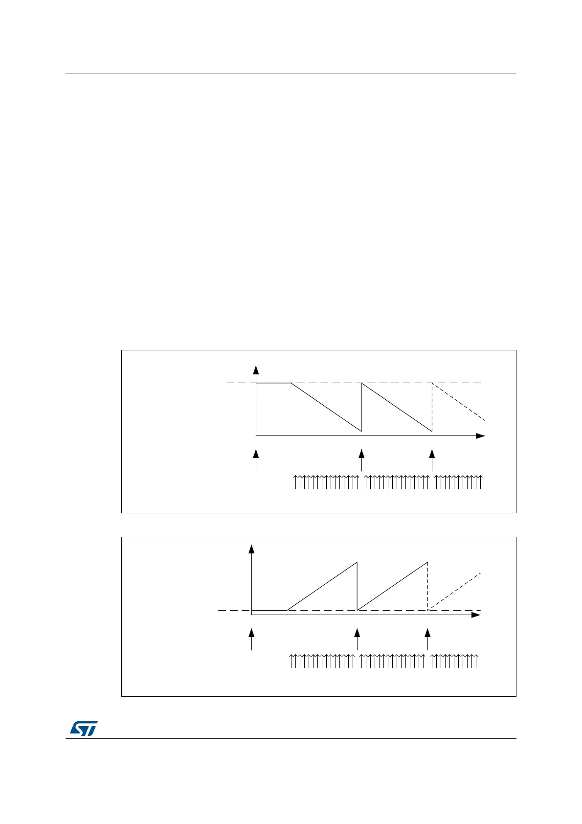
22.4.11 DAC sawtooth wave generation
The DAC can generate a sawtooth waveform. Specific register settings for the initial value,
increment value and direction control are required:
• DAC sawtooth wave generation is selected by setting WAVEx[1:0] to 11 in the
DAC_CR register.
• The sawtooth counter initial value (reset value) is configured through
STRSTDATAx[11:0] bits in the DAC_STRx register.
• The increment value is defined by the STINCDATAx[15:0] bits in the DAC_STRx
register.
• The sawtooth direction is defined by STDIRx bit in the DAC_STRx register.
The sawtooth counter starts from STRSTDATAx[11:0] (bits 12 to 15 are set to 0000), each
increment trigger then increments (or decrements) STINCDATAx[15:0] value.
The DAC output is used from 12 MSB of those counter value. When the counter reaches
0x0000 or 0xFFFF, the value is saturated. The sawtooth reset trigger signal initializes the
counter value to the STRSTDATAx[11:0] (bits 12 to 15 are set to 0000) value.
The increment trigger and reset trigger must be selected through the STINCTRIGSELx[3:0]
and the STRSTTRIGSELx[3:0] bits.
Figure 164. DAC sawtooth wave generation (STDIRx=0)
Figure 165. DAC sawtooth wave generation (STDIRx=1)
MSv46131V1
0
STRSTDATA[11:0]
Value
STRSTTRIG signal
STINCTRIG signal
MSv46130V1
0
STRSTDATA[11:0]
value
STRSTTRIG signal
STINCTRIG signal