RM0440 Rev 4 1771/2126
RM0440 Serial peripheral interface / integrated interchip sound (SPI/I2S)
1791
The appropriate transition is a falling edge on WS signal when I
2
S Philips Standard is used,
or a rising edge for other standards. The falling edge is detected by sampling first WS to 1
and then to 0, and vice-versa for the rising edge detection.
If ASTRTEN = 1, the user has to enable the audio interface before the WS becomes active.
This means that the I2SE bit must be set to 1 when WS = 1 for I
2
S Philips standard, or when
WS = 0 for other standards.
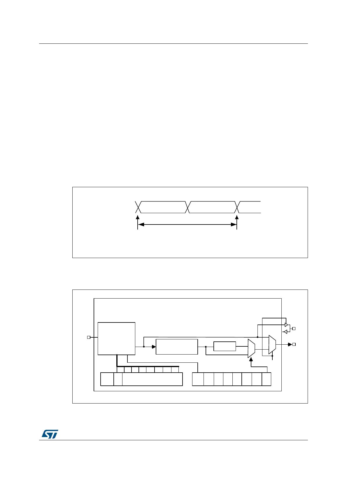
39.7.4 Clock generator
The I
2
S bit rate determines the data flow on the I
2
S data line and the I
2
S clock signal
frequency.
I
2
S bit rate = number of bits per channel × number of channels × sampling audio frequency
For a 16-bit audio, left and right channel, the I
2
S bit rate is calculated as follows:
I
2
S bit rate = 16 × 2 × f
S
It is: I
2
S bit rate = 32 x 2 x f
S
if the packet length is 32-bit wide.
Figure 606. Audio sampling frequency definition
When the master mode is configured, a specific action needs to be taken to properly
program the linear divider in order to communicate with the desired audio frequency.
Figure 607. I
2
S clock generator architecture
1. Where x can be 2 or 3.
MS30108V1
16-or 32-bit left
channel
16-or 32-bit
right channel
32- or 64-bits
sampling point
sampling point
F
S
F
S
: audio sampling frequency
MS30109V1
MCKOE
ODD
8-bit linear divider
+ reshaping stage
Divider by 4
Div2
I²SDIV[7:0]
I²SMOD
CHLEN
0
1
0
1
MCKOE
CK
MCK
I²SxCLK