Cyclic redundancy check calculation unit (CRC) RM0440
462/2126 RM0440 Rev 4
16.3 CRC functional description
16.3.1 CRC block diagram
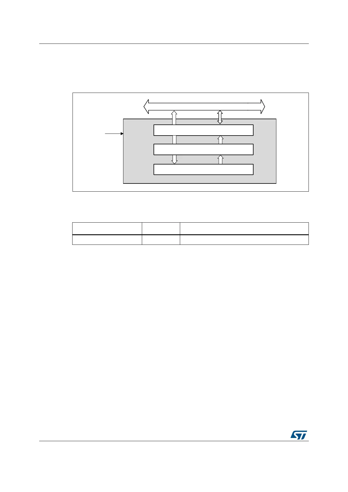
Figure 37. CRC calculation unit block diagram
16.3.2 CRC internal signals
16.3.3 CRC operation
The CRC calculation unit has a single 32-bit read/write data register (CRC_DR). It is used to
input new data (write access), and holds the result of the previous CRC calculation (read
access).
Each write operation to the data register creates a combination of the previous CRC value
(stored in CRC_DR) and the new one. CRC computation is done on the whole 32-bit data
word or byte by byte depending on the format of the data being written.
The CRC_DR register can be accessed by word, right-aligned half-word and right-aligned
byte. For the other registers only 32-bit access is allowed.
The duration of the computation depends on data width:
• 4 AHB clock cycles for 32-bit
• 2 AHB clock cycles for 16-bit
• 1 AHB clock cycles for 8-bit
An input buffer allows a second data to be immediately written without waiting for any wait
states due to the previous CRC calculation.
The data size can be dynamically adjusted to minimize the number of write accesses for a
given number of bytes. For instance, a CRC for 5 bytes can be computed with a word write
followed by a byte write.
MS19882V2
Data register (output)
32-bit (read access)
Data register (input)
32-bit (write access)
32-bit AHB bus
crc_hclk
CRC computation
Table 100. CRC internal input/output signals
Signal name Signal type Description
crc_hclk Digital input AHB clock