RM0440 Rev 4 917/2126
RM0440 High-resolution timer (HRTIM)
1083
The level of the output in IDLE state is configured using IDLESx bit in HRTIM_OUTxR, as
follows:
• 0: output at inactive level when in IDLE
• 1: output at active level when in IDLE
When TxyOEN bit is set to enter the RUN state, the output is immediately connected to the
crossbar output. If the timer clock is stopped, the level is either inactive (after an HRTIM
reset) or corresponds to the RUN level (when the timer is stopped and the output disabled).
During the HRTIM initialization, the output level can be prepositioned prior to have it in RUN
mode, using the software forced output set and reset in the HRTIM_SETx1R and
HRTIM_RSTx1R registers.
27.3.15 Burst mode controller
The burst mode controller allows to have the outputs alternatively in IDLE and RUN state, by
hardware, so as to skip some switching periods with a programmable periodicity and duty
cycle.
Burst mode operation is of common use in power converters when operating under light
loads. It can significantly increase the efficiency of the converter by reducing the number of
transitions on the outputs and the associated switching losses.
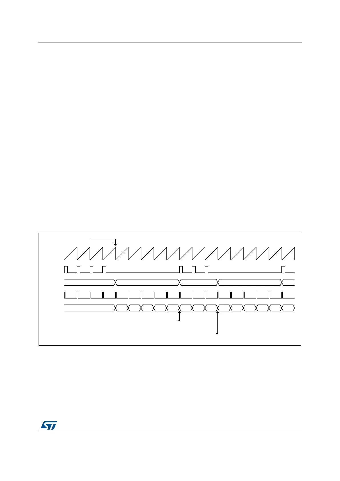
When operating in burst mode, one or a few pulses are outputs followed by an idle period
equal to several counting periods, typically, where no output pulses are produced, as shown
in the example on Figure 236.
Figure 236. Burst mode operation example
The burst mode controller consists of:
• A counter that can be clocked by various sources, either within or outside the HRTIM
(typically the end of a PWM period).
• A compare register to define the number of idle periods: HRTIM_BMCMP.
• A period register to define the burst repetition rate (corresponding to the sum of the idle
and run periods): HRTIM_BMPER.
MS32283V1
IDLE RUN IDLE
Counter
Output
Output
state
RUN
10 2 3 4 5 6 70 1 2 3 4 50
Burst
counter
Burst Trigger
HRTIM_BMCMP = 4
HRTIM_BMPER = 7
Burst
clock