Inter-integrated circuit (I2C) interface RM0440
1904/2126 RM0440 Rev 4
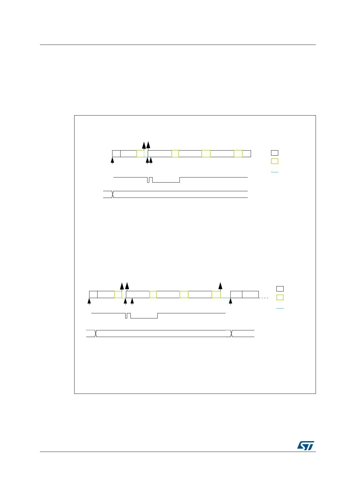
When the SMBus master wants to send a RESTART condition after the PEC, software
mode must be selected (AUTOEND=0). In this case, once NBYTES-1 have been
transmitted, the I2C_PECR register content is transmitted and the TC flag is set after the
PEC transmission, stretching the SCL line low. The RESTART condition must be
programmed in the TC interrupt subroutine.
Caution: The PECBYTE bit has no effect when the RELOAD bit is set.
Figure 657. Bus transfer diagrams for SMBus master transmitter
MS19871V2
Example SMBus master transmitter 2 bytes + PEC, automatic end mode (STOP)
Address
S
INIT: program Slave address, program NBYTES = 3, AUTOEND=1, set PECBYTE, set START
EV1: TXIS ISR: wr data1
EV2: TXIS ISR: wr data2
A
data1
A
TXIS
TXIS
data2
A
NBYTES
A
legend:
transmission
reception
SCL stretch
EV1
xx 3
INIT
Example SMBus master transmitter 2 bytes + PEC, software end mode (RESTART)
INIT: program Slave address, program NBYTES = 3, AUTOEND=0, set PECBYTE, set START
EV1: TXIS ISR: wr data1
EV2: TXIS ISR: wr data2
EV3: TC ISR: program Slave address, program NBYTES = N, set START
NBYTES
Rstart
legend:
transmission
reception
SCL stretch
xx
Address
N
PEC
P
EV2
A
3
TXE
Address
S
A
data1
A
TXIS TXIS
data2
A
EV1
INIT
PEC
EV2
TC
EV3
 Loading...


