RM0440 Rev 4 2019/2126
RM0440 Universal serial bus full-speed device interface (USB)
2041
The memory buffer which is currently being used by the USB peripheral is defined by DTOG
buffer flag, while the buffer currently in use by application software is identified by SW_BUF
buffer flag. The relationship between the buffer flag value and the used packet buffer is the
same in both cases, and it is listed in the following table.
Double-buffering feature for a bulk endpoint is activated by:
• Writing EP_TYPE bit field at ‘00 in its USB_EPnR register, to define the endpoint as a
bulk, and
• Setting EP_KIND bit at ‘1 (DBL_BUF), in the same register.
The application software is responsible for DTOG and SW_BUF bits initialization according
to the first buffer to be used; this has to be done considering the special toggle-only property
that these two bits have. The end of the first transaction occurring after having set
DBL_BUF, triggers the special flow control of double-buffered bulk endpoints, which is used
for all other transactions addressed to this endpoint until DBL_BUF remain set. At the end of
each transaction the CTR_RX or CTR_TX bit of the addressed endpoint USB_EPnR
register is set, depending on the enabled direction. At the same time, the affected DTOG bit
in the USB_EPnR register is hardware toggled making the USB peripheral buffer swapping
completely software independent. Unlike common transactions, and the first one after
Table 408. Double-buffering buffer flag definition
Buffer flag ‘Transmission’ endpoint ‘Reception’ endpoint
DTOG DTOG_TX (USB_EPnR bit 6) DTOG_RX (USB_EPnR bit 14)
SW_BUF USB_EPnR bit 14 USB_EPnR bit 6
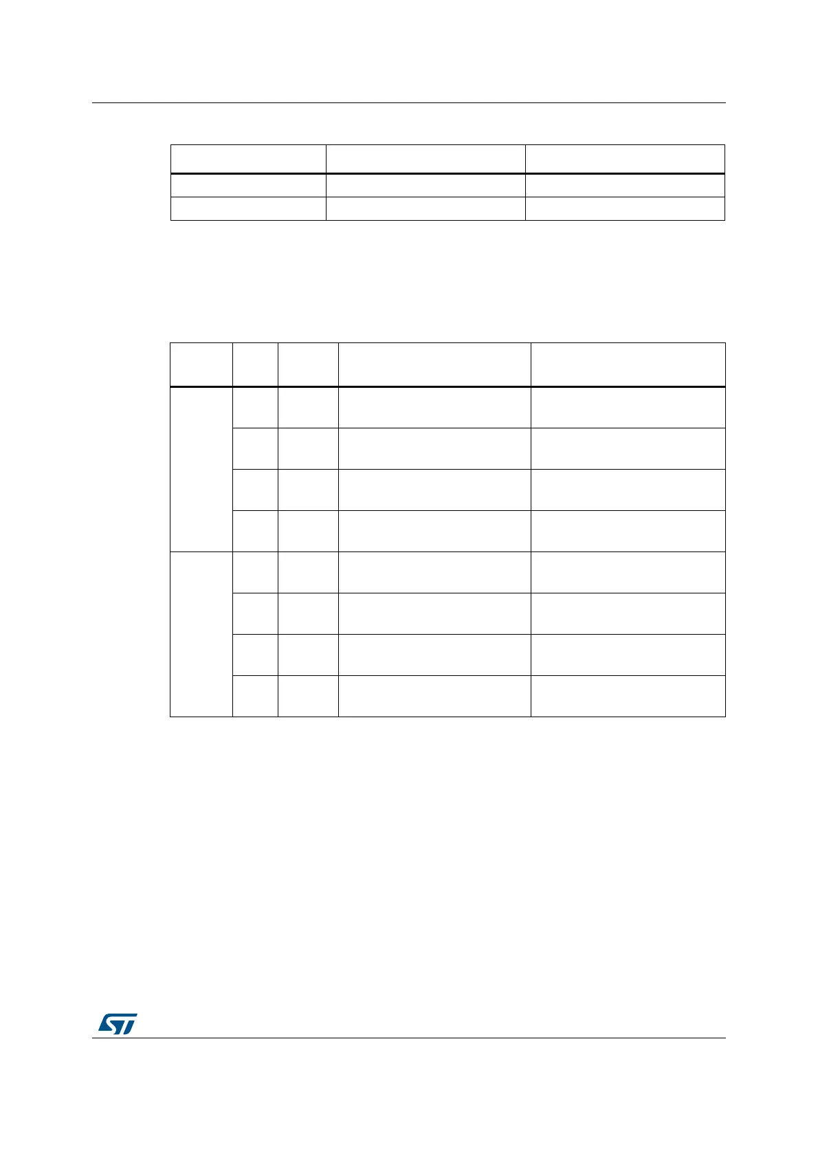
Table 409. Bulk double-buffering memory buffers usage
Endpoint
type
DTOG SW_BUF
Packet buffer used by
USB peripheral
Packet buffer used by
Application Software
IN
01
ADDRn_TX_0 / COUNTn_TX_0
Buffer description table locations.
ADDRn_TX_1 / COUNTn_TX_1
Buffer description table locations.
10
ADDRn_TX_1 / COUNTn_TX_1
Buffer description table locations
ADDRn_TX_0 / COUNTn_TX_0
Buffer description table locations.
0 0 None
(1)
1. Endpoint in NAK Status.
ADDRn_TX_0 / COUNTn_TX_0
Buffer description table locations.
1 1 None
(1)
ADDRn_TX_0 / COUNTn_TX_0
Buffer description table locations.
OUT
01
ADDRn_RX_0 / COUNTn_RX_0
Buffer description table locations.
ADDRn_RX_1 / COUNTn_RX_1
Buffer description table locations.
10
ADDRn_RX_1 / COUNTn_RX_1
Buffer description table locations.
ADDRn_RX_0 / COUNTn_RX_0
Buffer description table locations.
0 0 None
(1)
ADDRn_RX_0 / COUNTn_RX_0
Buffer description table locations.
1 1 None
(1)
ADDRn_RX_1 / COUNTn_RX_1
Buffer description table locations.