Serial audio interface (SAI) RM0440
1816/2126 RM0440 Rev 4
Clock generator programming in AC’97 mode
In AC’97 mode, the frame length is fixed at 256 bits, and its frequency shall be set to
48 kHz. The formulas given in Section 40.3.8: SAI clock generator shall be used with FRL =
255, in order to generate the proper frame rate (F
FS_x)
.
40.3.12 SPDIF output
The SPDIF interface is available in transmitter mode only. It supports the audio IEC60958.
To select SPDIF mode, set PRTCFG[1:0] bit to 01 in the SAI_xCR1 register.
For SPDIF protocol:
• Only SD data line is enabled.
• FS, SCK, MCLK I/Os pins are left free.
• MODE[1] bit is forced to 0 to select the master mode in order to enable the clock
generator of the SAI and manage the data rate on the SD line.
• The data size is forced to 24 bits. The value set in DS[2:0] bits in the SAI_xCR1 register
is ignored.
• The clock generator must be configured to define the symbol-rate, knowing that the bit
clock should be twice the symbol-rate. The data is coded in Manchester protocol.
• The SAI_xFRCR and SAI_xSLOTR registers are ignored. The SAI is configured
internally to match the SPDIF protocol requirements as shown in Figure 622.
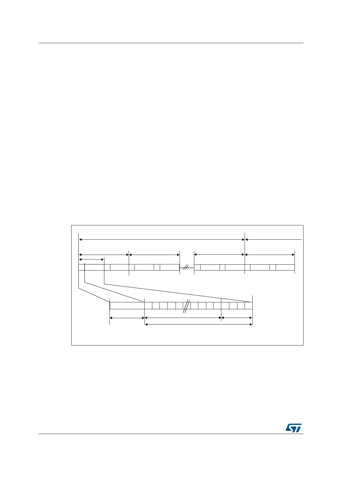
Figure 622. SPDIF format
A SPDIF block contains 192 frames. Each frame is composed of two 32-bit sub-frames,
generally one for the left channel and one for the right channel. Each sub-frame is
composed of a SOPD pattern (4-bit) to specify if the sub-frame is the start of a block (and so
is identifying a channel A) or if it is identifying a channel A somewhere in the block, or if it is
referring to channel B (see Table 368). The next 28 bits of channel information are
composed of 24 bits data + 4 status bits.
B
Frame 0 Frame 1 Frame 0
Sub-frame
SOPD
D0 D1
D2 D3
D4 D20
D21
D22 D23
VP
CS
U
SOPD B,M,W
Channel
Block N
Block N+1
Frame 191
24-bit data
Status bit
Channel A
W
Channel B M
Channel A
W
Channel B
M
Channel A
W
Channel B B
Channel A
W
Channel B
MS30042V1