RM0440 Rev 4 927/2126
RM0440 High-resolution timer (HRTIM)
1083
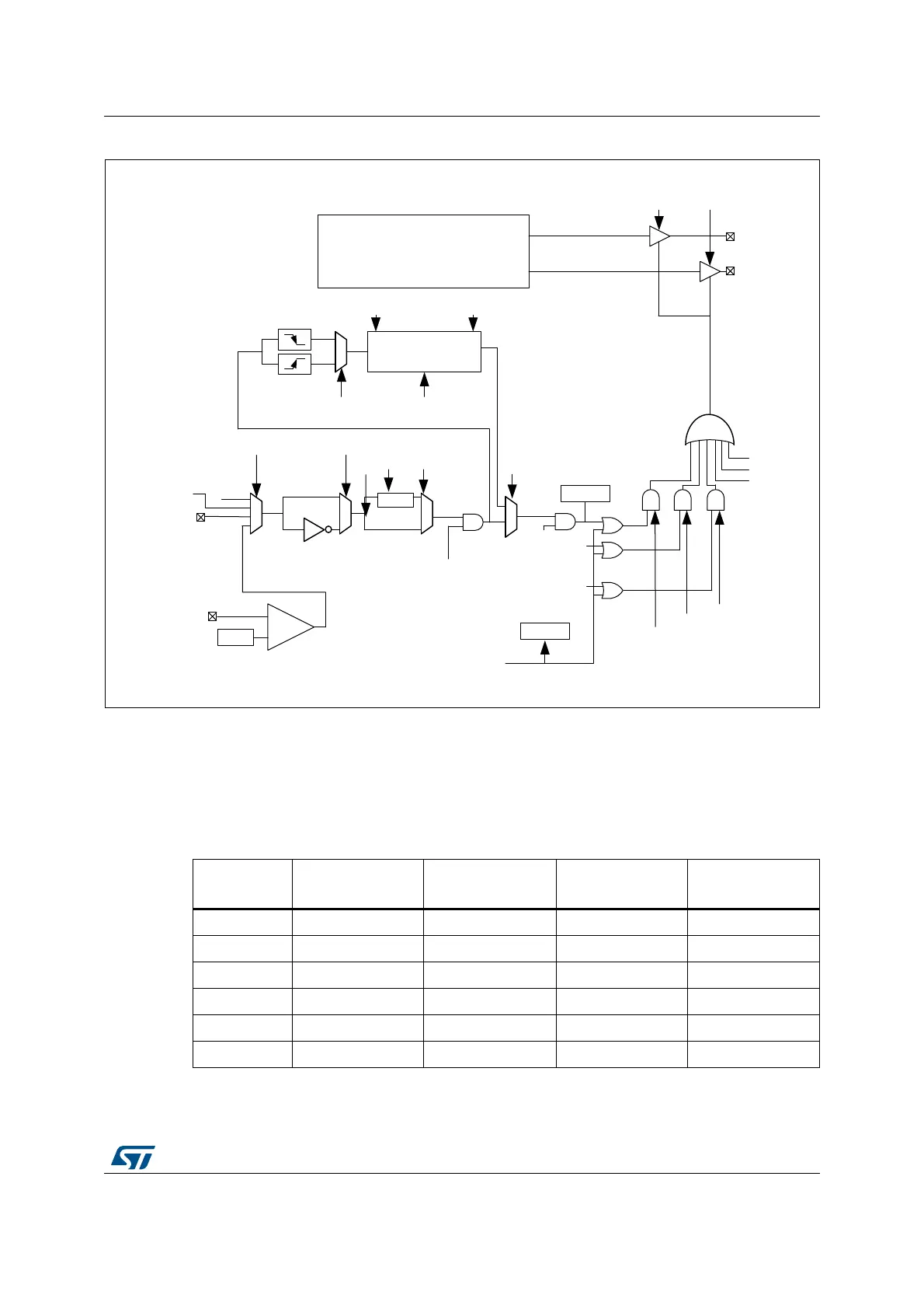
Figure 244. Fault protection circuitry (FAULT1 fully represented, FAULT2..6 partially)
Each fault channel is fully configurable using HRTIM_FLTINR1 and HRTIM_FLTINR2
registers before being routed to the timing units. FLTxSRC FLTxSRC[1:0] bit selects the
source of the fault signal, that can be either a digital input or an internal event (built-in
comparator output).
Table 233 and Table 211 summarize the available sources for each of the 6 faults channels:
MSv48377V2
FLT1
Timer x
HRTIM_FLT[1]
COMPin
+
-
FLT1SRC[1:0]
FLT1F[3:0]
FLT1P
FLT1E
HRTIM_CHx1
HRTIM_CHx2
FAULT2[1:0]FAULT1[1:0]
FLT1EN
FLT2EN
FLT3EN
Fault3
Fault2
SYSFLT
f
FLTS
Fault 5
Fault 4
Polarity
Filter
DAC
EEV1_muxout
N/A
Blanking
sources
hrtim_sys_flt
FLT1CNT[3:0]
Fault 6
Counter
FLT1CNT[3:0]
FLT1P
FLT1RSTM FLT1CRES
hrtim_in_flt[1]
Table 233. Fault inputs
Fault channel
External Input
FLTxSRC[1:0] = 00
On-chip source
FLTxSRC[1:0] = 01
External Input
FLTxSRC[1:0] = 10
On-chip source
FLTxSRC[1:0] = 11
hrtim_flt1[4:1] HRTIM_FLT1 Comparator output EEV1_muxout N/A
hrtim_flt2[4:1] HRTIM_FLT2 Comparator output EEV2_muxout N/A
hrtim_flt3[4:1] HRTIM_FLT3 Comparator output EEV3_muxout N/A
hrtim_flt4[4:1] HRTIM_FLT4 Comparator output EEV4_muxout N/A
hrtim_flt5[4:1] HRTIM_FLT5 Comparator output EEV5_muxout N/A
hrtim_flt6[4:1] HRTIM_FLT6 Comparator output EEV6_muxout N/A