Power control (PWR) RM0440
236/2126 RM0440 Rev 4
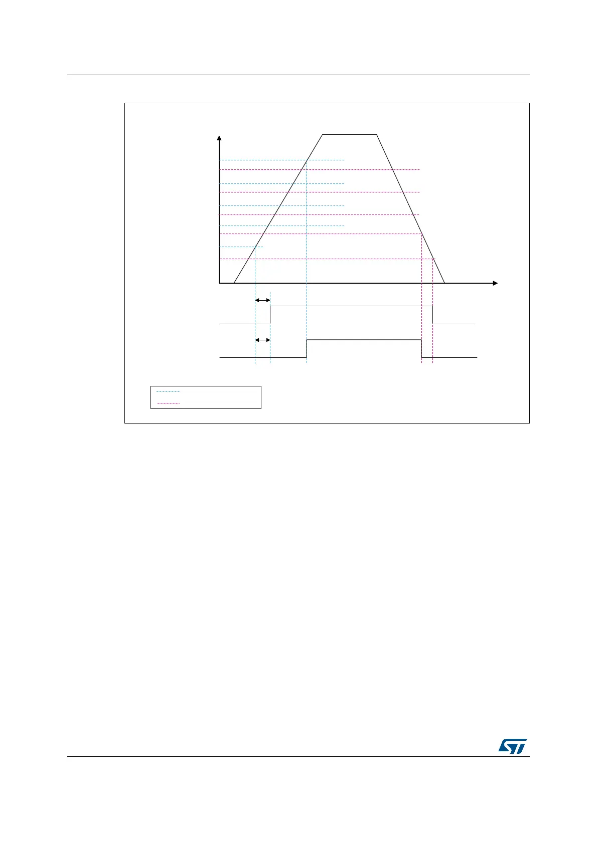
Figure 13. Brown-out reset waveform
1. The reset temporization t
RSTTEMPO
is present only for the BOR lowest threshold (V
BOR0
).
6.2.2 Programmable voltage detector (PVD)
You can use the PVD to monitor the V
DD
power supply by comparing it to a threshold
selected by the PLS[2:0] bits in the Power control register 2 (PWR_CR2).
The PVD is enabled by setting the PVDE bit.
A PVDO flag is available, in the Power status register 2 (PWR_SR2), to indicate if V
DD
is
higher or lower than the PVD threshold. This event is internally connected to the EXTI line16
and can generate an interrupt if enabled through the EXTI registers. The PVD output
interrupt can be generated when V
DD
drops below the PVD threshold and/or when V
DD
rises above the PVD threshold depending on EXTI line16 rising/falling edge configuration.
As an example, the service routine could perform emergency shutdown tasks.
MSv45389V4
V
DD
V
BORR4
V
BORF4
V
BORR3
V
BORF3
V
BORR2
V
BORF2
V
BORR1
V
BORF1
V
POR
V
PDR
t
t
RSTTEMPO
t
RSTTEMPO
Reset with BOR off
Reset with BOR on
(V
BORR4
V
BORF1
)
POR/BOR rising thresholds
PDR/BOR falling thresholds