RM0440 Rev 4 89/2126
RM0440
91
2.5 Flash memory overview
The Flash memory is composed of two distinct physical areas:
• The main Flash memory block. It contains the application program and user data if
necessary.
• The information block. It is composed of three parts:
– Option bytes for hardware and memory protection user configuration.
– System memory that contains the ST proprietary code.
– OTP (one-time programmable) area
The Flash interface implements instruction access and data access based on the AHB
protocol. It also implements the logic necessary to carry out the Flash memory operations
(program/erase) controlled through the Flash registers. Refer to Section 3: Embedded Flash
memory (FLASH) for category 3 devices, Section 5: Embedded Flash memory (FLASH) for
category 2 devices and Section 5: Embedded Flash memory (FLASH) for category 2
devices for more details.
2.6 Boot configuration
2.6.1 Boot configuration
Three different boot modes can be selected through the BOOT0 pin or the nBOOT0 bit into
the FLASH_OPTR register (if the nSWBOOT0 bit is cleared into the FLASH_OPTR
register), and nBOOT1 bit in FLASH_OPTR register, as shown in the following table.
The values on both BOOT0 pin (coming from the pin or the option bit) and nBOOT1 bit are
latched on the 4th edge of the internal startup clock source after reset release. It is up to the
user to set nBOOT1 and BOOT0 to select the required boot mode.
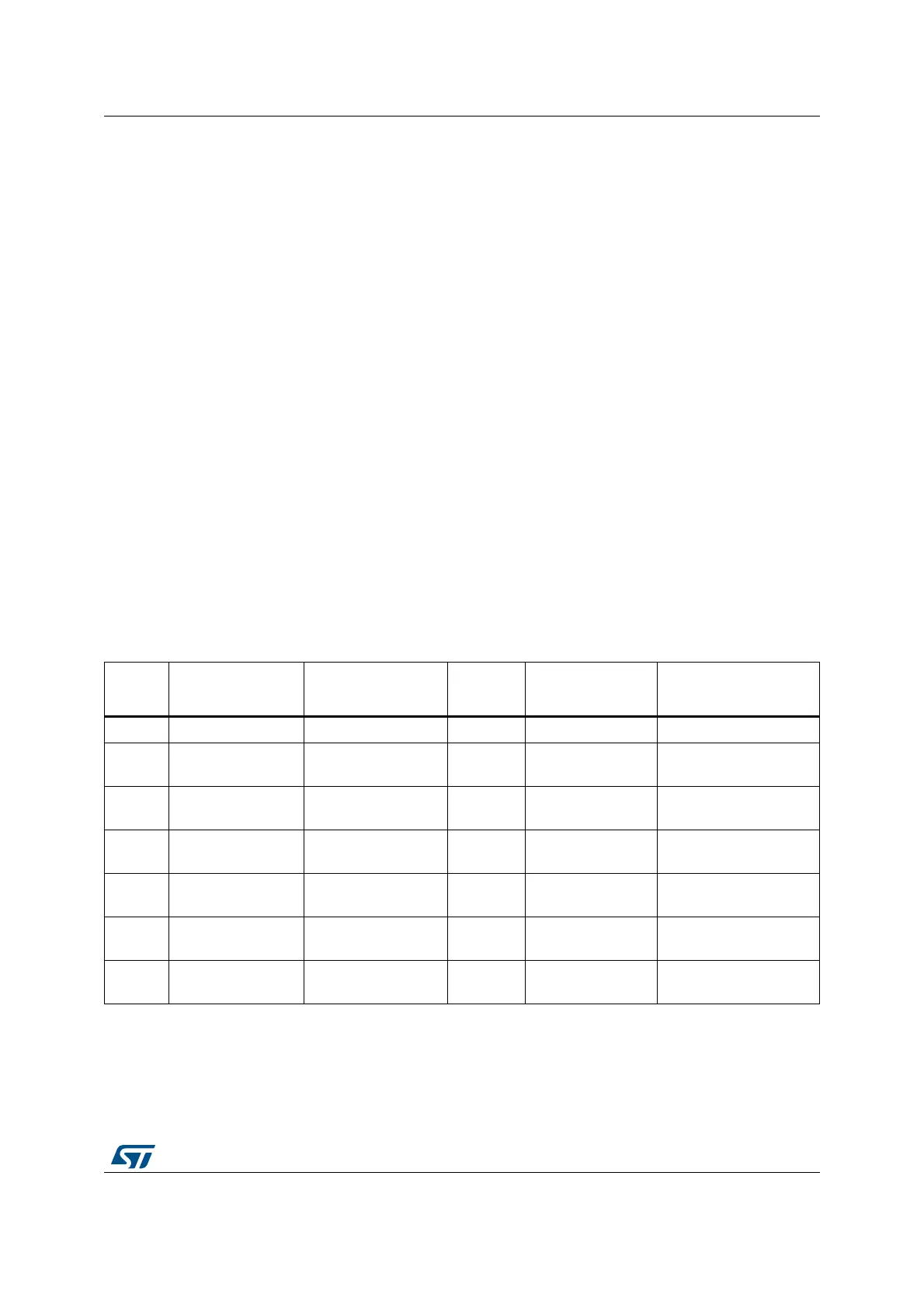
Table 5. Boot modes
BOOT_
LOCK
nBOOT1
FLASH_OPTR[23]
nBOOT0
FLASH_OPTR[27]
BOOT0
pin PB8
nSWBOOT0
FLASH_OPTR[26]
Boot Memory Space
Alias
1 X X X X Main Flash memory
0X X 0 1
Main Flash memory is
selected as boot area
0X 1 X 0
Main Flash memory is
selected as boot area
00 X 1 1
Embedded SRAM1 is
selected as boot area
00 0 X 0
Embedded SRAM1 is
selected as boot area
01 X 1 1
System memory is
selected as boot area
01 0 X 0
System memory is
selected as boot area