RM0440 Rev 4 855/2126
RM0440 High-resolution timer (HRTIM)
1083
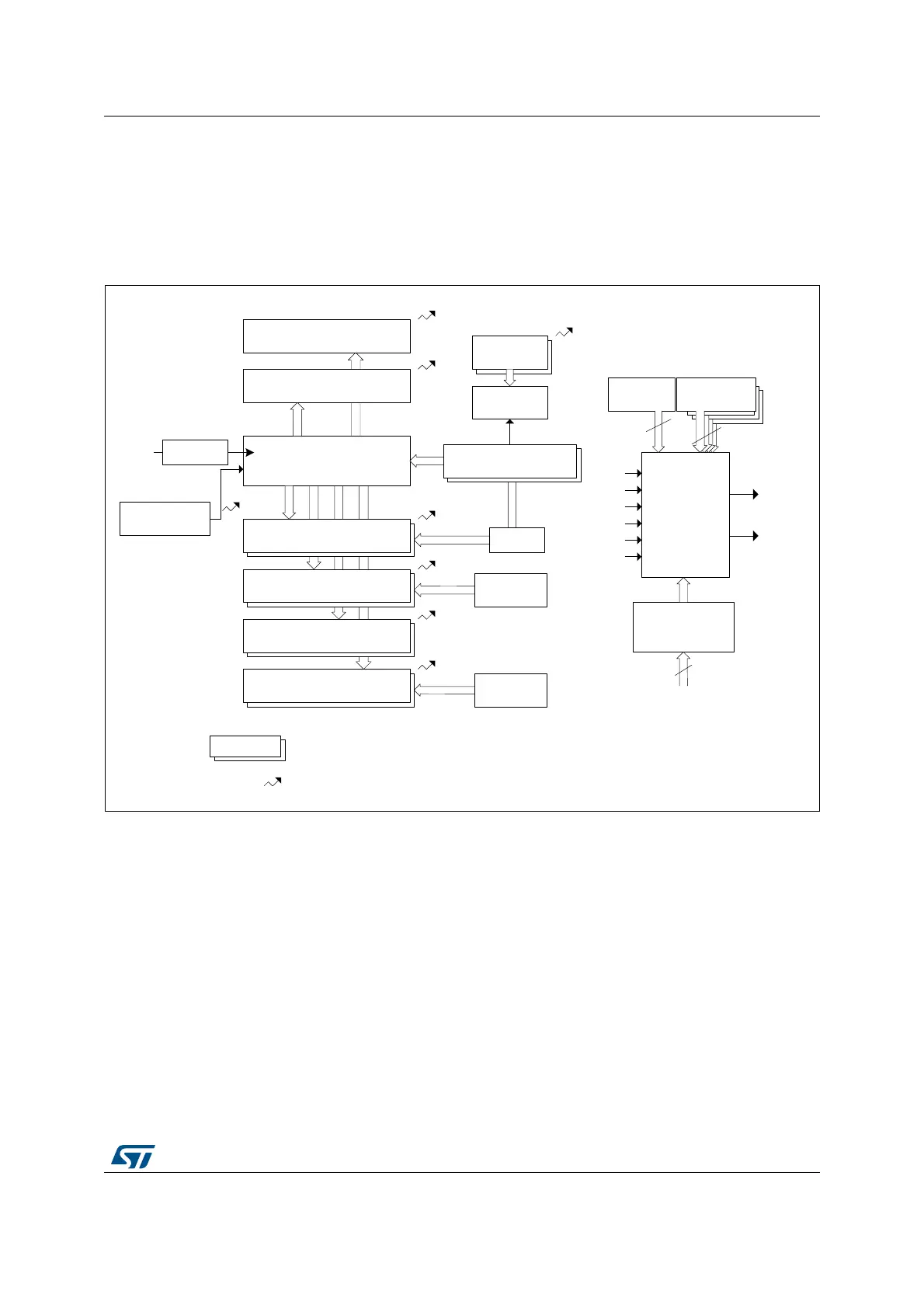
27.3.4 Timer A..F timing units
The HRTIM embeds 6 identical timing units made of a 16-bit up-counter with an auto-reload
mechanism to define the counting period, 4 compare and 2 capture units, as per Figure 184.
Each unit includes all control features for 2 outputs, so that it operates as a standalone
timer.
Figure 184. Timer A..F overview
The period and compare values must be within a lower and an upper limit related to the
high-resolution implementation and listed in Table 214:
• The minimum value must be greater than or equal to 3 periods of the f
HRTIM
clock. The
value 0x0000 can be written in CMP1 and CMP3 registers only, to skip a PWM pulse.
See Section : Null duty cycle exception case for details
• The maximum value must be less than or equal to 0xFFFF - 1 periods of the f
HRTIM
clock.
MS32258V1
Master
timer
Master
timer
Master
timer
Capture 2
Counter
Prescaler
Capture 1
Compare 2
Compare 1
Compare 3
Compare 4
Period
Counter
Half
Repetition
Autodelay
Register
Autodelay
CMP1
CMP2
CMP3
CMP4
CPT1
CPT2
REP
Reset
Management
RST
Denotes a register with preload
Interrupt / DMA request
f
HRTIM
Set / reset
crossbar
(2 outputs)
Push-pull
and deadtime
management
Events
Blanking and
windowing
Master
timer
Out 1
Out 2
To the
output
stage
Other
timing units
REP
CMP1
CMP2
CMP3
CMP4
Update
6
9
10
From external events
conditioning