RM0440 Rev 4 745/2126
RM0440 Digital-to-analog converter (DAC)
773
To disabled the output buffer, MODEx[2:0] bits in DAC_MCR register must be set to:
• 110: DAC is connected to external pin and to on chip peripherals
• 111: DAC is connected to on chip peripherals
When MODEx[2:0] bits are equal to 111, an internal capacitor, C
Lint
, holds the voltage
output of the DAC core and then drive it to on-chip peripherals.
All Sample and hold phases are interruptible, and any change in DAC_DHRx immediately
triggers a new sample phase.
Note: The sawtooth wave generation is not supported in Sample and hold mode operation.
22.4.13 DAC channel buffer calibration
The transfer function for an N-bit digital-to-analog converter (DAC) is:
Where V
OUT
is the analog output, D is the digital input, G is the gain, V
ref
is the nominal full-
scale voltage, and V
os is the offset voltage. For an ideal DAC channel, G = 1 and Vos = 0.
Due to output buffer characteristics, the voltage offset may differ from part-to-part and
introduce an absolute offset error on the analog output. To compensate the V
os, a calibration
is required by a trimming technique.
The calibration is only valid when the DAC channelx is operating with buffer enabled
(MODEx[2:0] = 000b or 001b or 100b or 101b). if applied in other modes when the buffer is
off, it has no effect. During the calibration:
• The buffer output is disconnected from the pin internal/external connections and put in
tristate mode (HiZ).
• The buffer acts as a comparator to sense the middle-code value 0x800 and compare it
to VREF+/2 signal through an internal bridge, then toggle its output signal to 0 or 1
depending on the comparison result (CAL_FLAGx bit).
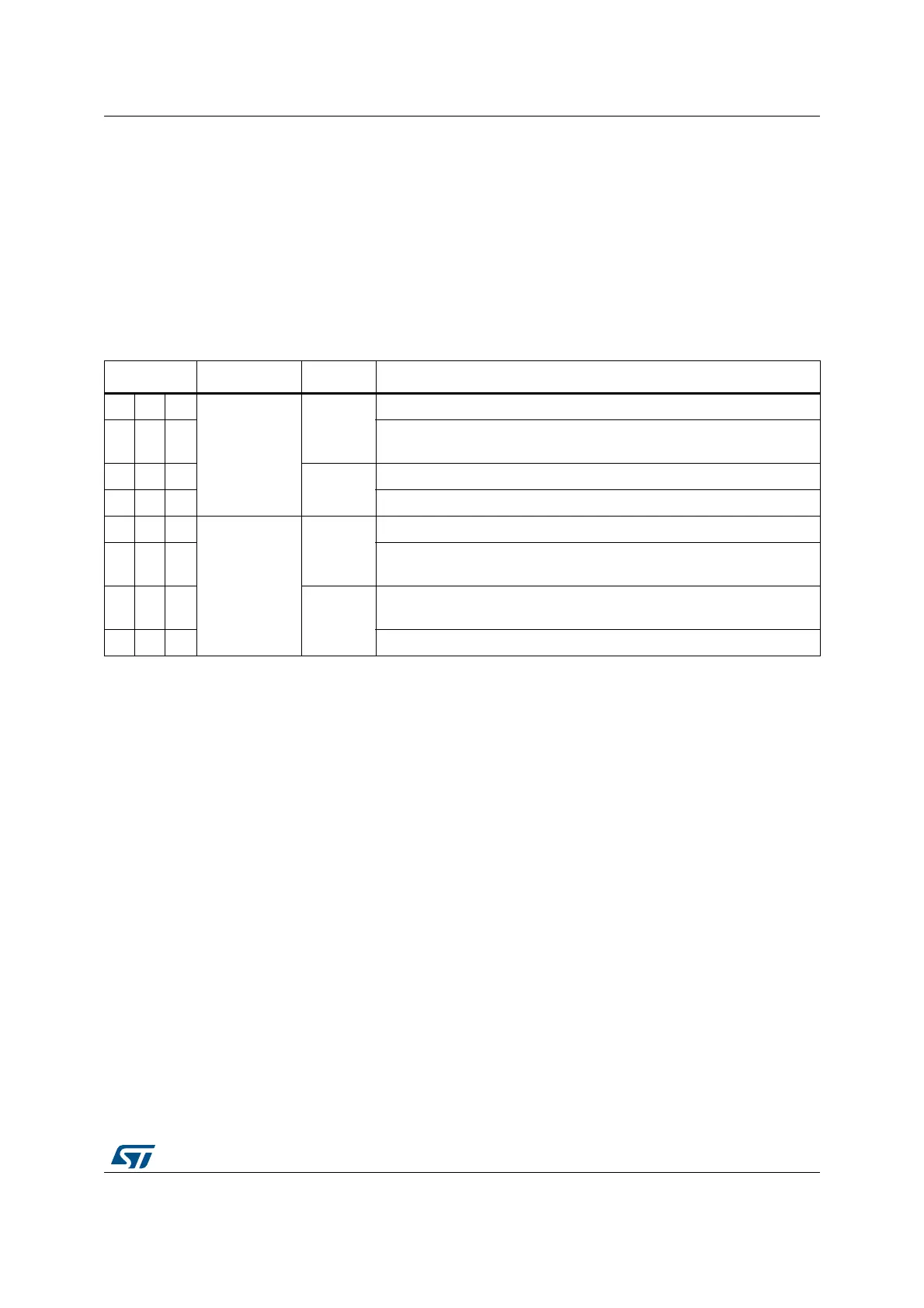
Table 189. Channel output modes summary
MODEx[2:0] Mode Buffer Output connections
000
Normal mode
Enabled
Connected to external pin
001
Connected to external pin and to on chip-peripherals (such as
comparators)
010
Disabled
Connected to external pin
0 1 1 Connected to on chip peripherals (such as comparators)
100
Sample and
hold mode
Enabled
Connected to external pin
101
Connected to external pin and to on chip peripherals (such as
comparators)
110
Disabled
Connected to external pin and to on chip peripherals (such as
comparators)
1 1 1 Connected to on chip peripherals (such as comparators)
V
out
D2
N1–
⁄()GV
ref
××()V
OS
+=