RM0440 Rev 4 795/2126
RM0440 Operational amplifiers (OPAMP)
829
25.3.7 Calibration
The OPAMP offset value is minimized using a trimming circuitry. At startup, the trimming
values are initialized with the preset ‘factory’ trimming value. Each operational amplifier can
also be trimmed by the user if the OPAMP is used in conditions different from the factory
trimming conditions.
Each operational amplifier can be trimmed by the user. Specific registers allow to have
different trimming values for normal mode and for high-speed mode.
The aim of the calibration is to cancel as much as possible the OPAMP inputs offset voltage.
The calibration circuitry allows to reduce the input offset voltage to less than +/-3 mV within
stable voltage and temperature conditions.
For each operational amplifier and two trimming values (TRIMOFFSETP and
TRIMOFFSETN in OPAMPx_CSR register) need to be trimmed, one for N differential pair
and one for P differential pair.
The user is able to switch from ‘factory’ values to ‘user’ trimmed values using the
USERTRIM bit in the OPAMPx_CSR register. This bit is reset at startup and so the ‘factory’
value are applied by default to the OPAMP option registers.
The offset trimming TRIMOFFSETP and TRIMOFFSETN bits are typically configured after
the calibration operation is initialized by setting bit CALON to 1. When CALON = 1 the inputs
of the operational amplifier are disconnected from the I/Os.
• Setting CALSEL to 01 initializes the offset calibration for the P differential pair (low
voltage reference used).
• Resetting CALSEL to 11 initializes the offset calibration for the N differential pair (high
voltage reference used).
When CALON = 1, the bit CALOUT reflects the influence of the trimming value selected by
CALSEL and OPAHSM. The software must increment the TRIMOFFSETN bits in the
OPAMP control register from 0x00 to the first value that causes the CALOUT bit to change
from 1 to 0 in the OPAMP register. If the CALOUT bit is reset, the offset is calibrated
correctly and the corresponding trimming value must be stored. The CALOUT flag needs up
to 1 ms after the trimming value is changed to become steady (see t
OFFTRIM
max delay
specification in the electrical characteristics section of the datasheet).
Note: The closer the trimming value is to the optimum trimming value, the longer it takes to
stabilize (with a maximum stabilization time remaining below 1 ms in any case).
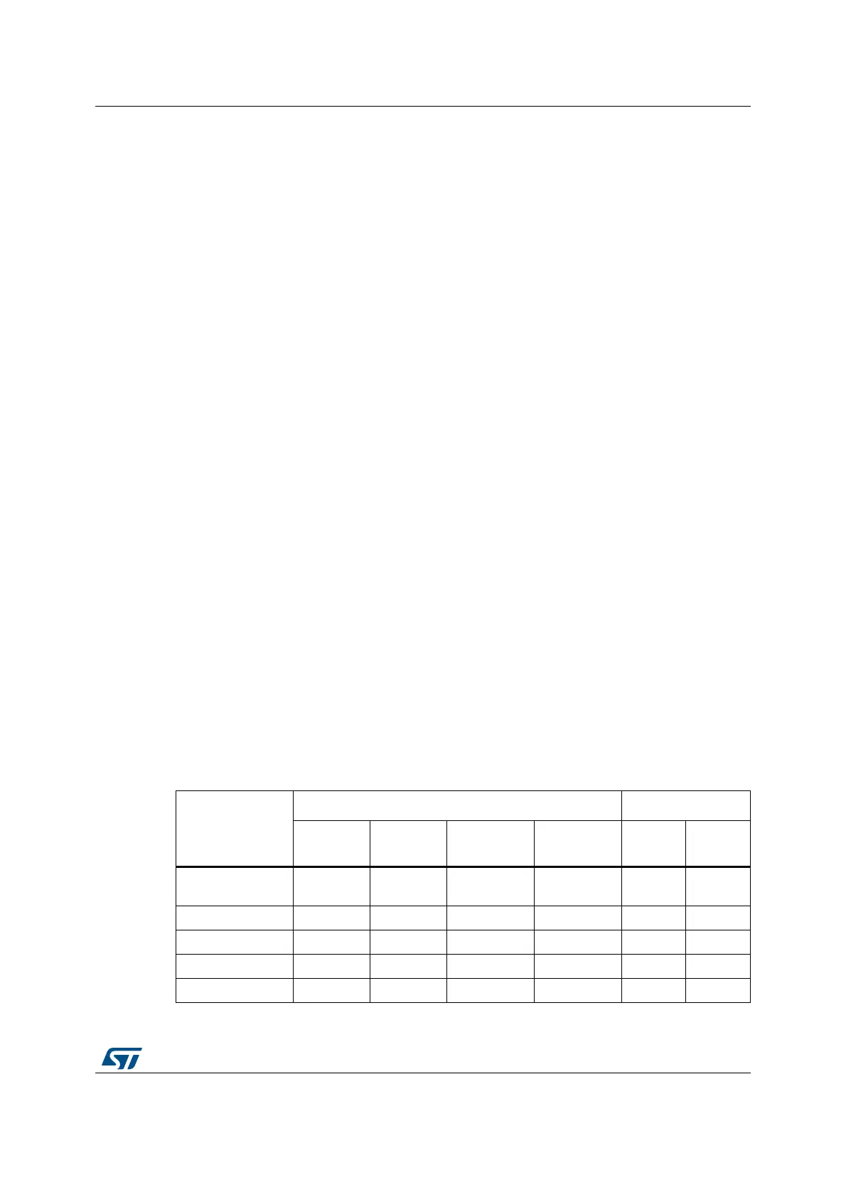
Table 201. Operating modes and calibration
Mode
Control bits Output
OPAEN OPAHSM CALON CALSEL V
OUT
CALOUT
flag
Normal operating
mode
1 0 0 X analog 0
High-speed mode 1 1 0 X analog 0
Power down 0 X X X Z 0
Offset cal N 1 X 1 11 analog X
Offset cal P diff 1 X 1 01 analog X