RM0440 Rev 4 951/2126
RM0440 High-resolution timer (HRTIM)
1083
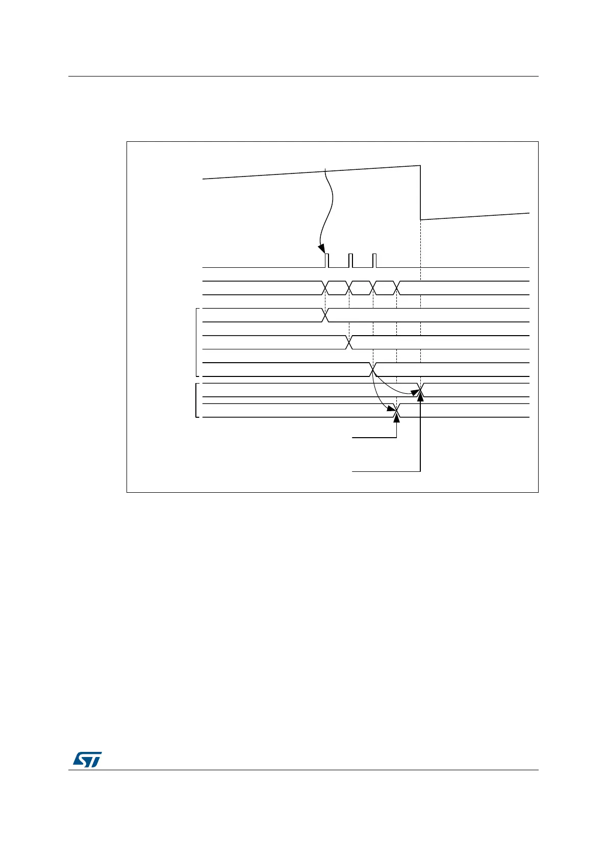
The chronogram on Figure 260 presents the active register content for 3 cases: PREEN=0,
UPDGAT[3:0] = 0001 and UPDGAT[3:0] = 0001 (when PREEN = 1).
Figure 260. Registers update following DMA burst transfer
27.3.24 HRTIM initialization
This section describes the recommended HRTIM initialization procedure, including other
related MCU peripherals.
The HRTIM clock source must be enabled in the reset and clock control unit (RCC), while
respecting the
fHRTIM
range for the DLL lock.
The DLL calibration must be started by setting CAL bit in HRTIM_DLLCR register.
The HRTIM master and timing units can be started only once the high-resolution unit is
ready. This is indicated by the DLLRDY flag set. The DLLRDY flag can be polled before
resuming the initialization or the calibration can run in background while other registers of
the HRTIM or other MCU peripherals are initialized. In this case, the DLLRDY flag must be
checked before starting the counters (an end-of-calibration interrupt can be issued if
necessary, enabled with DLLRDYIE flag in HRTIM_IER). Once the DLL calibration is done,
CALEN bit must be set to have it done periodically and compensate for potential voltage
and temperature drifts. The calibration periodicity is defined using the CALRTE[1:0] bitfield
in the HRTIM_DLLCR register.
MS32342V1
PER CMP1 CMP3
PER (previous)
CMP1 (previous)
CMP3 (previous)
PER (new)
CMP1 (new)
CMP3 (new)
CMP3 (previous)
DMA request on CMP1 event
starts DMA burst
Register content
PREEN=0
Register content
PREEN=1
(CMP3 showed only)
CMP3 (previous)
CMP3 (new)
CMP3 (new)
DMA requests
DMA controller write
accesses to BDMADR
Timer A
Counter
Option 1: update done at the end of the DMA burst
transfer (UPDGAT[3:0] = 0001)
Option 2: update done at the end of the DMA burst
transfer (UPDGAT[3:0] = 0010 and TxREPU = 1
Repetition
event