RM0440 Rev 4 1281/2126
RM0440 General-purpose timers (TIM2/TIM3/TIM4/TIM5)
1343
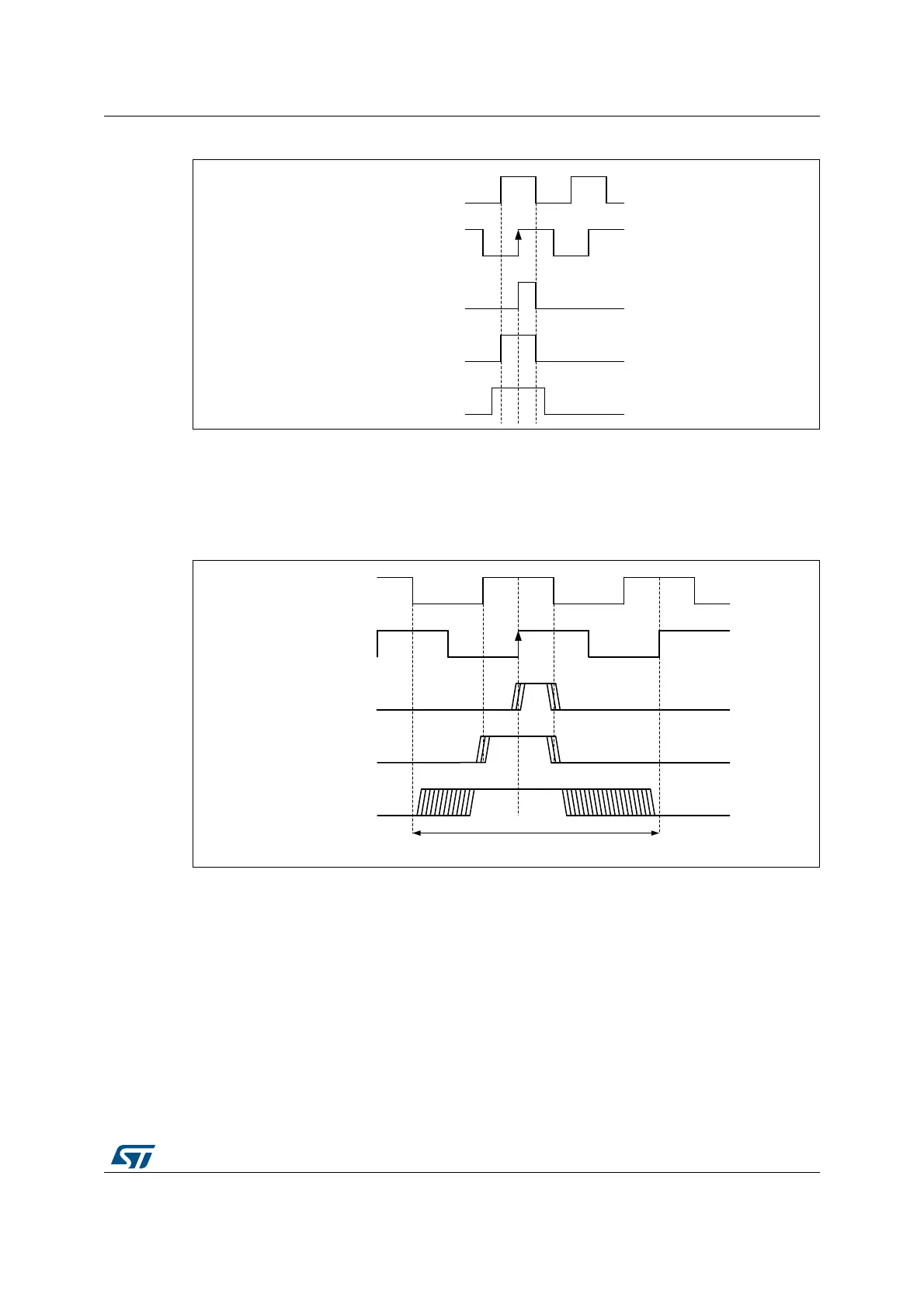
Figure 411. Index gating options
The circuitry tolerates jitter on index signal, whatever the gating mode, as show on
Figure 412 below.
In ungated mode, the signal must be strictly below 2 encoder periods. If the pulse width is
greater or equal to 2 encoder period, the counter will be reset multiple times.
Figure 412. Jittered Index signals
The timer supports the 3 gating options identically, without any specific programming
needed. It is only necessary to define on which encoder state (i.e. channel A and channel B
state combination) the index must be synchronized, using the IPOS[1:0] bitfield in the
TIMx_ECR register.
The Index detection event will act differently depending on counting direction to ensure
symmetrical operation during speed reversal:
• The counter is reset during up-counting (DIR bit = 0)
• The counter is set to TIMx_ARR when down counting
This allows the index to be generated on the very same mechanical angular position
whatever the counting direction. The Figure 413 below shows at which position is the index
generated, for a simplistic example (an encoder providing 4 edges par mechanical rotation).
MSv45765V1
Gated A & B
Gated A
Ungated
Channel B
Channel A
MSv45766V1
Gated A & B
Gated A
Ungated
Channel B
Channel A
Max pulsewidth ungated mode
 Loading...


