Advanced-control timers (TIM1/TIM8/TIM20) RM0440
1170/2126 RM0440 Rev 4
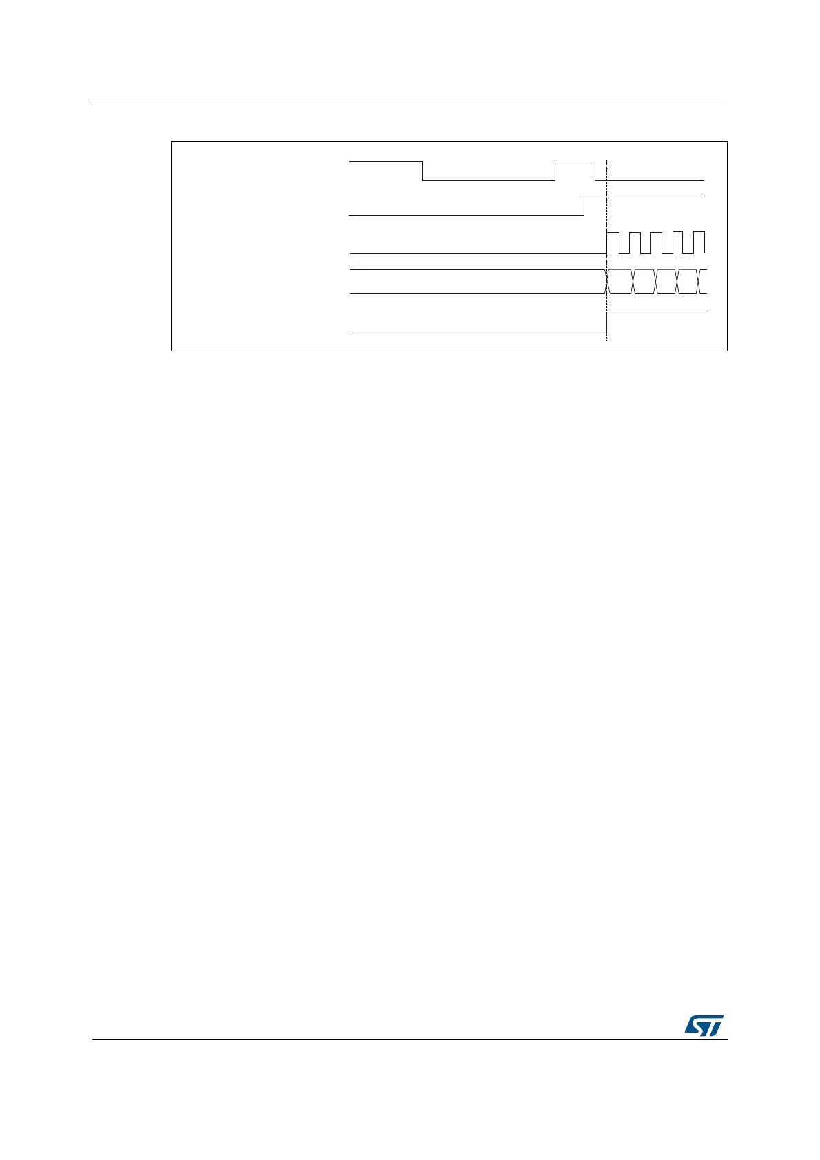
Figure 356. Control circuit in trigger mode
Slave mode: Combined reset + trigger mode
In this case, a rising edge of the selected trigger input (tim_trgi) reinitializes the counter,
generates an update of the registers, and starts the counter.
This mode is used for one-pulse mode.
Slave mode: Combined gated + reset mode
The counter clock is enabled when the trigger input (tim_trgi) is high. The counter stops and
is reset) as soon as the trigger becomes low. Both start and stop of the counter are
controlled.
This mode allows to detect out-of-range PWM signal (duty cycle exceeding a maximum
expected value).
Slave mode: external clock mode 2 + trigger mode
The external clock mode 2 can be used in addition to another slave mode (except external
clock mode 1 and encoder mode). In this case, the tim_etr_in signal is used as external
clock input, and another input can be selected as trigger input (in reset mode, gated mode
or trigger mode). It is recommended not to select tim_etr_in as tim_trgi through the TS bits
of TIMx_SMCR register.
In the following example, the upcounter is incremented at each rising edge of the tim_etr_in
signal as soon as a rising edge of tim_ti1 occurs:
MSv62363V1
37
Counter register
38
34
35 36
TIF
tim_ti2
CEN
tim_cnt_ck, tim_psc_ck
 Loading...


