RM0440 Rev 4 957/2126
RM0440 High-resolution timer (HRTIM)
1083
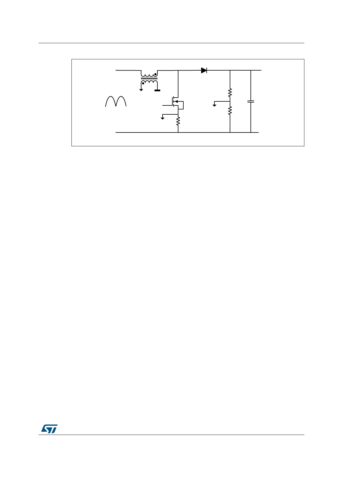
Figure 267. Transition mode PFC
This converter operates with a constant Ton time and a variable frequency due the Toff time
variation (depending on the input voltage). It must also include some features to operate
when no zero-crossing is detected, or to limit the Ton time in case of over-current (OC). The
OC feedback is usually conditioned with the built-in comparator and routed onto an external
event input.
Figure 268 presents the waveform during the various operating modes, with the following
defined parameters:
• Ton Min: masks spurious overcurrent (freewheeling diode recovery current),
represented as OC blanking
• Ton Max: practically, the converter set-point. It is defined by CMP1
• Toff Min: limits the frequency when the current limit is close to zero (demagnetization is
very fast). It is defined with CMP2.
• Toff Max: prevents the system to be stuck if no ZCD occurs. It is defined with CMP4 in
auto-delayed mode.
Both Toff values are auto-delayed since the value must be relative to the output falling edge.
MS32349V3
V
OUT
ADC
HRTIM_
CHA2
V
IN
ZCD
OC