RM0440 Rev 4 1865/2126
RM0440 Inter-integrated circuit (I2C) interface
1928
I2C timings
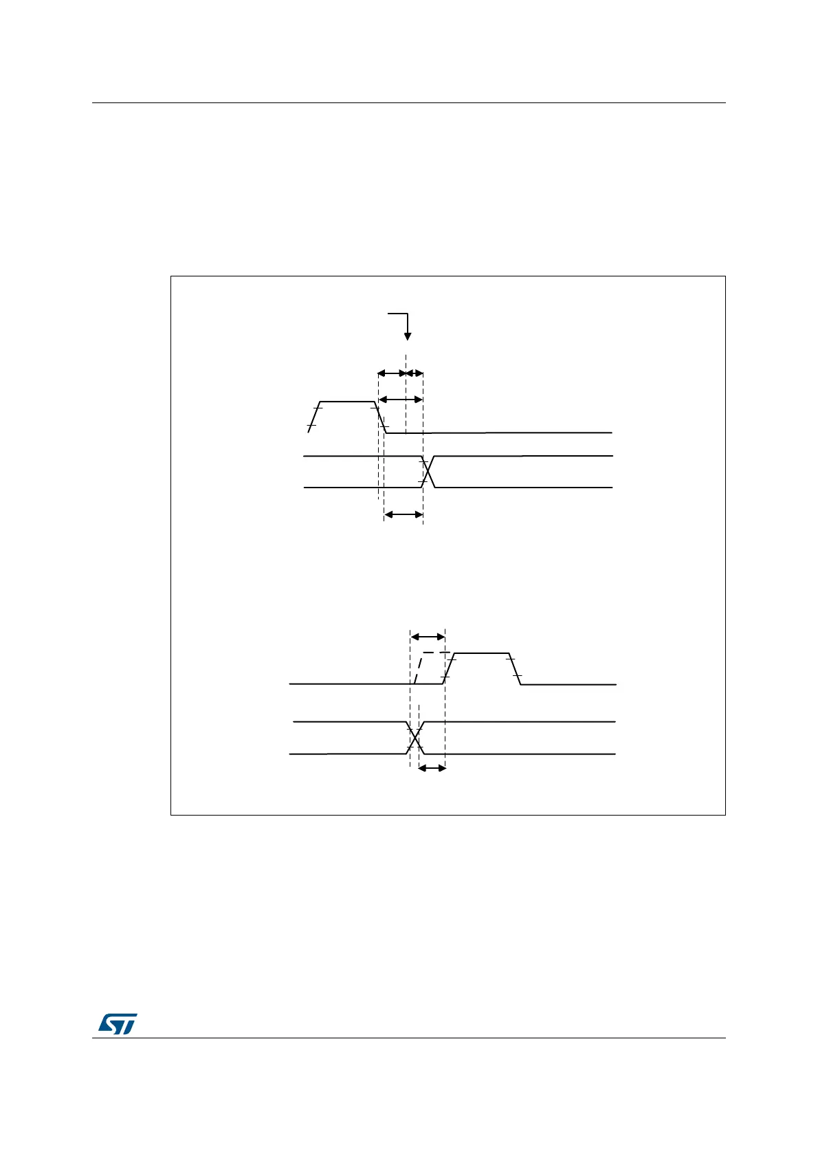
The timings must be configured in order to guarantee a correct data hold and setup time,
used in master and slave modes. This is done by programming the PRESC[3:0],
SCLDEL[3:0] and SDADEL[3:0] bits in the I2C_TIMINGR register.
The STM32CubeMX tool calculates and provides the I2C_TIMINGR content in the I2C
configuration window
Figure 631. Setup and hold timings
MSv40108V1
t
SYNC1
SCL falling edge internal
detection
SDADEL: SCL stretched low by the I2C
SDA output delay
SCL
SDA
DATA HOLD TIME
t
HD;DAT
SCLDEL
SCL stretched low by the I2C
SCL
SDA
DATA SETUP TIME
t
SU;STA
Data hold time: in case of transmission, the data is sent on SDA output after
the SDADEL delay, if it is already available in I2C_TXDR.
Data setup time: in case of transmission, the SCLDEL counter starts
when the data is sent on SDA output.
MS49608V1
t
SYNC1
SCL falling edge internal
detection
SDADEL: SCL stretched low by the I2C
SDA output delay
SCL
SDA
DATA HOLD TIME
t
HD;DAT
SCLDEL
SCL stretched low by the I2C
SCL
SDA
DATA SETUP TIME
t
SU;DAT
Data hold time: in case of transmission, the data is sent on SDA output after
the SDADEL delay, if it is already available in I2C_TXDR.
Data setup time: in case of transmission, the SCLDEL counter starts
when the data is sent on SDA output.