RM0440 Rev 4 1141/2126
RM0440 Advanced-control timers (TIM1/TIM8/TIM20)
1226
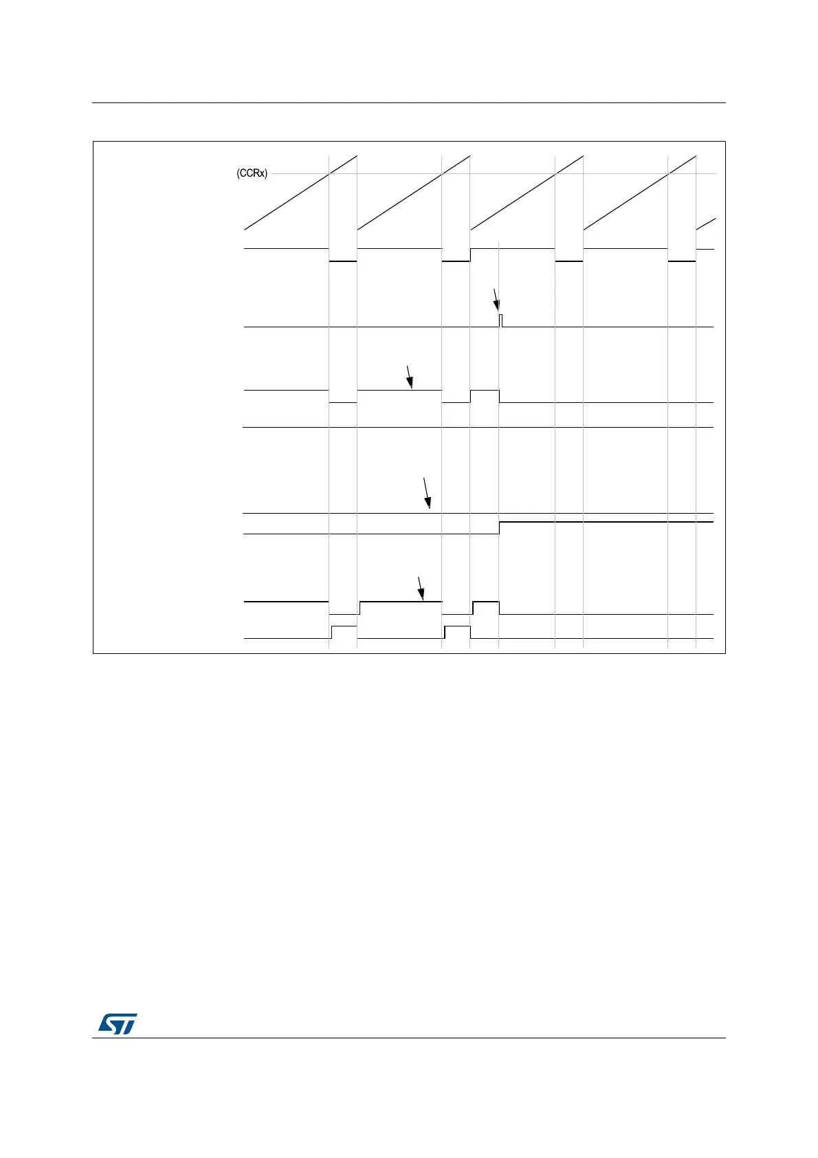
Figure 323. 6-step generation, COM example (OSSR=1)
28.3.22 One-pulse mode
One-pulse mode (OPM) is a particular case of the previous modes. It allows the counter to
be started in response to a stimulus and to generate a pulse with a programmable length
after a programmable delay.
Starting the counter can be controlled through the slave mode controller. Generating the
waveform can be done in output compare mode or PWM mode. One-pulse mode is selected
by setting the OPM bit in the TIMx_CR1 register. This makes the counter stop automatically
at the next update event UEV.
A pulse can be correctly generated only if the compare value is different from the counter
initial value. Before starting (when the timer is waiting for the trigger), the configuration must
be:
• In upcounting: CNT < CCRx ≤ ARR (in particular, 0 < CCRx)
• In downcounting: CNT > CCRx
MSv62343V1
Example 1
Example 2
Example 3
tim_ocx
tim_ocxn
tim_ocx
tim_ocxn
tim_ocx
tim_ocxn
Counter (CNT)
tim_ocxref
COM event
Write COM to 1
CCxE = 1
CCxNE = 0
OCxM = 0010 (forced inactive)
Write OCxM to 0100
CCxE = 1
CCxNE = 0
OCxM = 0100
CCxE = 1
CCxNE = 0
OCxM = 0100 (forced inactive)
Write CCxNE to 1
and OCxM to 0101
CCxE = 0
CCxNE = 1
OCxM = 0101
CCxE = 1
CCxNE = 0
OCxM = 0010 (forced inactive)
Write CCxNE to 0
and OCxM to 0100
CCxE = 1
CCxNE = 1
OCxM = 0100