General-purpose timers (TIM2/TIM3/TIM4/TIM5) RM0440
1280/2126 RM0440 Rev 4
Index Input
The counter can be reset by an Index signal coming from the encoder, indicating an
absolute reference position. The Index signal must be connected to the tim_etr_in input. It
can be filtered using the digital input filter.
The index functionality is enabled with the IE bit in the TIMx_ECR register. The IE bit must
be set only in encoder mode, when the SMS[3:0] bitfield has the following values: 0001,
0010, 011, 1010, 1011, 1100, 1101, 1110, 1111.
Commercially available encoders are proposed with several options for index pulse
conditioning, as per the Figure 411 below:
• gated with A and B: the pulse width is 1/4 of one channel period, aligned with both A
and B edges
• gated with A (or gated with B): the pulse width is 1/2 of one channel period, aligned with
the two edges on channel A (resp. channel B)
• ungated: the pulse width is up to one channel period, without any alignment to the
edges
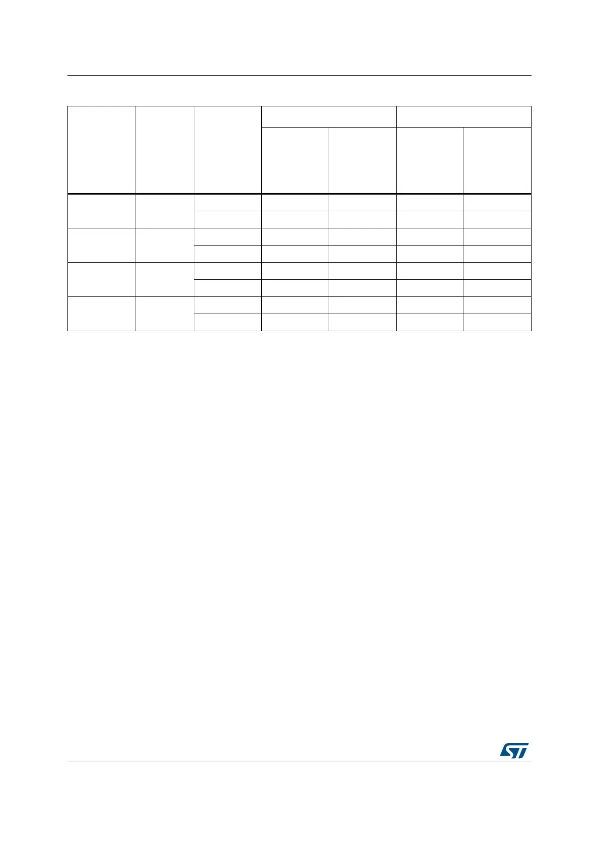
Table 280. Counting direction versus encoder signals and polarity settings
Directional
clock mode
SMS[3:0]
Level on
opposite
signal
(tim_ti1fp1 for
tim_ti2,
tim_ti2fp2 for
tim_ti1)
tim_ti1fp1 signal tim_ti2fp2 signal
Rising Falling Rising Falling
x2 mode
CCxP=0
1100
High Down Down Up Up
Low No count No count No count No count
x2 mode
CCxP=1
1100
High No count No count No count No count
Low Down Down Up Up
x1 mode
CCxP=0
1101
High No count Down No count Up
Low No count No count No count No count
x1 mode
CCxP=1
1101
High No count No count No count No count
Low Down No count Up No count

 Loading...