General-purpose timers (TIM2/TIM3/TIM4/TIM5) RM0440
1234/2126 RM0440 Rev 4
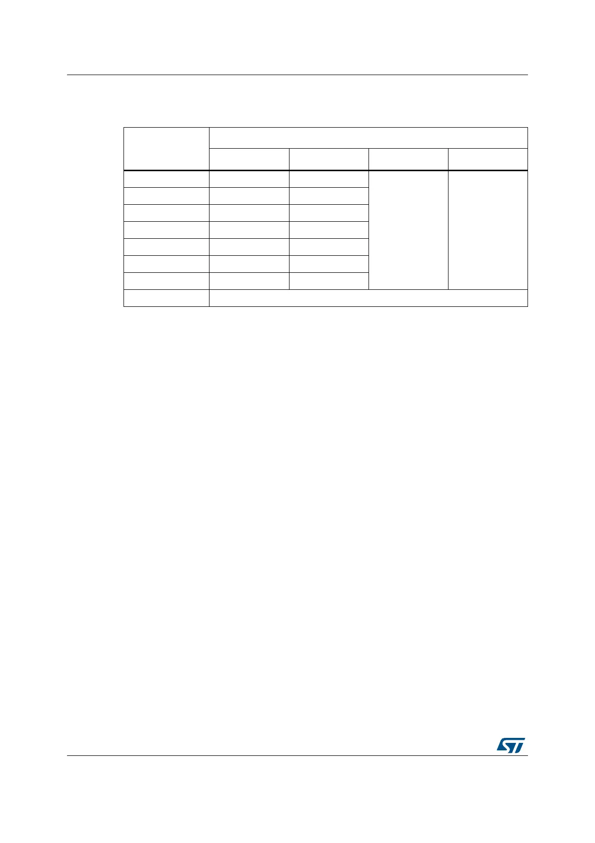
Table 276 lists the internal sources connected to the tim_ocref_clr input multiplexer.
29.4.3 Time-base unit
The main block of the programmable timer is a 16-bit/32-bit counter with its related auto-
reload register. The counter can count up, down or both up and down but also down or both
up and down. The counter clock can be divided by a prescaler.
The counter, the auto-reload register and the prescaler register can be written or read by
software. This is true even when the counter is running.
The time-base unit includes:
• Counter Register (TIMx_CNT)
• Prescaler Register (TIMx_PSC):
• Auto-Reload Register (TIMx_ARR)
The auto-reload register is preloaded. Writing to or reading from the auto-reload register
accesses the preload register. The content of the preload register are transferred into the
shadow register permanently or at each update event (UEV), depending on the auto-reload
preload enable bit (ARPE) in TIMx_CR1 register. The update event is sent when the counter
reaches the overflow (or underflow when downcounting) and if the UDIS bit equals 0 in the
TIMx_CR1 register. It can also be generated by software. The generation of the update
event is described in detail for each configuration.
The counter is clocked by the prescaler output tim_cnt_ck, which is enabled only when the
counter enable bit (CEN) in TIMx_CR1 register is set (refer also to the slave mode controller
description to get more details on counter enabling).
Note that the actual counter enable signal CNT_EN is set 1 clock cycle after CEN.
Prescaler description
The prescaler can divide the counter clock frequency by any factor between 1 and 65536. It
is based on a 16-bit counter controlled through a 16-bit/32-bit register (in the TIMx_PSC
register). It can be changed on the fly as this control register is buffered. The new prescaler
ratio is taken into account at the next update event.
Table 276. Interconnect to the tim_ocref_clr input multiplexer
Timer
tim_ocref_clr
signal
Timer tim_ocref_clr signals assignment
TIM2 TIM3 TIM4 TIM5
tim_ocref_clr0 comp1_out comp1_out
Reserved Reserved
tim_ocref_clr1 comp2_out comp2_out
tim_ocref_clr2 comp3_out comp3_out
tim_ocref_clr3 comp4_out comp4_out
tim_ocref_clr4 comp5_out comp5_out
tim_ocref_clr5 comp6_out comp6_out
tim_ocref_clr6 comp7_out comp7_out
tim_ocref_clr7 Reserved